
06.3.3 / CDS Training Manual
Resolve a thick-panel
cure cycle and exotherm.
Use a published T700S/TC380 oven schedule to examine thermal lag, reaction heat, cure state, evolving modulus, and cycle optimization.
06.1 Manuals · read online, preview or download →
Current Workbench, reference editions and downloads
Use the online User Guide for current controls, the released model directory for selectable models and compatibility, and the Training Manual for connected exercises. Wider theory references do not mean every formulation is enabled in Workbench.
Screenshots and download editions carry revision dates; consult the current chapter for updated Workbench instructions. Find the overview PDF, guides and exercise databases in Your CDS library.
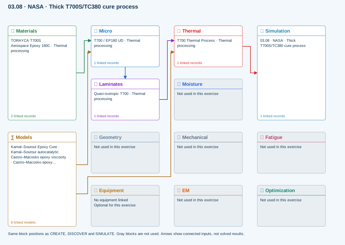
All blocks keep the CREATE / DISCOVER / SIMULATE positions, with Equipment below Geometry; unused records remain disconnected. This changes the view only, not the exercise records.
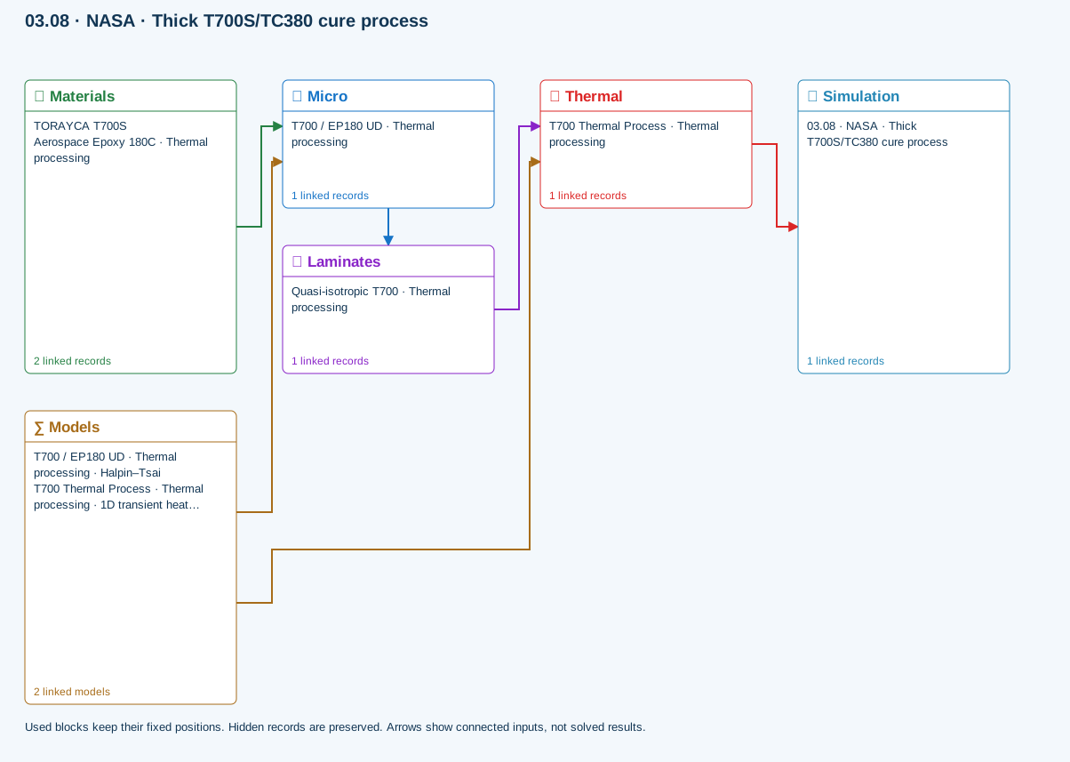
∑ Used models & submodels
Only models assigned to records used by this exercise are listed here. The full-layout option preserves the supplied starter records; no Workbench records are changed.
Halpin–Tsai · T700 / EP180 UD · Thermal processing
One compatible homogenization model per Micro recipe. Separate recipes compare models; their predictions are not blended.
∑ Theory & assumptions1D transient heat transfer · T700 Thermal Process · Thermal processing
Needs linked laminate properties and a compatible process schedule. A linked cycle is not a solved temperature history.
∑ Theory & assumptionsData travelling between blocks
Micro → Laminates
Predicted ply stiffness, strength, density and expansion properties.
Materials → Micro
Constituent stiffness, strength, density and thermal / moisture properties.
Thermal → Simulation
SIMULATION selects this case and its analysis model; the case owns its applicable cycle and input references.
Laminates → Thermal
Ply angles and thicknesses, stiffness, mass and ply properties.
Models → Micro
Applied model assignment: Halpin–Tsai. Model parameters and formulation are used by Micro.
Models → Thermal
Applied model assignment: 1D transient heat transfer. Model parameters and formulation are used by Thermal.
Reference validation · 2026-09-20
Not benchmark validated
No matched quantitative reference comparison completed for the full exercise.
Recorded baseline only—not a certification of the current database, edited inputs, or every output. Analytical agreement is not experimental material or failure validation.
Source validation, comparisons and tested inputs
Execution: Completed (not validation)
The starter resin and cycle are not TC380 calibration. The source supplies the schedule and measured checkpoints, but not all kinetics, heat-of-reaction or transport inputs. Source those inputs before a quantitative comparison.
- NASA — Evaluation of Temperature Gradients During Cure of a Thick Carbon Fiber/Epoxy Composite ↗Source study identified; quantitative reproduction not established. TC380 kinetics, reaction heat, transport, boundary characterization and digitized measurements still required.
Tested inputs
Input SHA-256: 55b3335c1c86a130941cab76e2594f7310aa4cc0e5c7f4426c14485eaab65655
Solver source SHA-256: 21b57ba5585334998ad98a0b2bac916764c93739a20e81f92e8e37cd50006f4a
- One-dimensional through-thickness study, not oven airflow or a general 3D process model. Missing TC380 calibration remains a setup requirement, never a default validated result.
Download source-validation results (JSON) · Full 138-exercise study
Model a 40-ply, 25.4 mm T700S/TC380 panel through a two-stage oven cure and determine how core lag and cure exotherm change the process window.
CDS reproduces a one-dimensional through-thickness process study. The NASA experiment supplies the cycle and thermal checkpoints; separate qualified data are required for kinetics, reaction heat and transport.
Published basis
2 primary sourcesReports T700S/TC380 braided panels, the recommended two-stage cure cycle, embedded thermocouples, exotherm, and through-thickness conversion differences.
↗NASA Tech BriefsDesigning Cure Cycles for Matrix/Fiber Composite PartsDescribes two-stage ramp-and-hold cure-cycle design as an optimization problem rather than trial and error.
↗Starting data
Enter in the displayed units| Variable | Value | How it is used |
|---|---|---|
| Panel | 40 plies; 25.4 mm | Published 1 inch thick comparison case |
| Ramp 1 | Room temperature → 107°C at 1.1°C/min | First oven segment |
| Dwell 1 | 107°C for 60 min | Intermediate hold |
| Ramp 2 | 107°C → 180°C at 1.1°C/min | Second oven segment |
| Dwell 2 | 180°C for 120 min | High-temperature hold |
| Cool | ≤ 3°C/min to < 49°C | Controlled cooldown |
Review checkpoints
Comparison, not certification| Result | Published reference | Interpretation |
|---|---|---|
| 40-ply exotherm above commanded cure temperature | 18°F ≈ 10°C | Published measured overshoot for the 40-ply panel |
| Maximum through-thickness variation | ≤ 10°C | Reported across the tested thicknesses |
| At 180°C: center conversion | approximately 85% | Published estimate at onset of vitrification |
| At 170°C: tool-side conversion | approximately 68% | Demonstrates cure-state mismatch through thickness |
138 exercises, examples and case studies → · Your CDS library: overview, manuals and database downloads →
Create the thick-panel baseline
Create a 40-ply T700S/TC380 laminate representing the 1 inch panel reported in the NASA thermal-gradient data.
Step-by-step instructions · 3 steps
- Use the linked TC380 cure-kinetics, reaction-heat and cure-dependent-modulus records when qualified inputs are available.
- Set total laminate thickness to 25.4 mm and assign through-thickness conductivity, density and specific heat from traceable records.
- Use enough through-thickness nodes to resolve the core and the two surfaces.
Enter the two-stage oven cycle
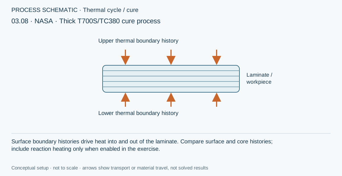
Build the published vacuum-bag-only schedule as a transient upper and lower boundary history.
Step-by-step instructions · 5 steps
- Start at the selected room reference temperature and ramp to 107°C at 1.1°C/min.
- Hold at 107°C for 60 minutes.
- Ramp to 180°C at 1.1°C/min and hold for 120 minutes.
- Cool at no more than 3°C/min until the part is below 49°C.
- Model the separate two-hour 180°C post-cure as a second cycle when it is included in the study.
Resolve thermal lag before adding reaction heat
Run the transient conduction model with cure exotherm disabled to establish the boundary-to-core lag.
Step-by-step instructions · 3 steps
- Plot oven or surface temperature with the core and tool-side node histories.
- Check the 107°C and 180°C transitions for adequate time resolution.
- Save the no-exotherm result as the conduction baseline.
Enable cure exotherm and evolving modulus
Turn on reaction heat and the cure-dependent modulus model, then rerun the same cycle.
Step-by-step instructions · 3 steps
- Compare peak core temperature, core-to-tool gradient and degree of cure with the baseline.
- Inspect when the core crosses the cure model’s gelation or vitrification transitions.
- Review the process-stress history only after the thermal and cure histories are credible.
Frame a process optimization
Duplicate the thermal case, including its own cycle, and optimize ramp or dwell variables against core-temperature and cure constraints.
Step-by-step instructions · 4 steps
- Choose a target core degree of cure and a maximum permitted core temperature or surface-to-core gradient.
- Allow the first ramp rate, intermediate dwell and second ramp rate to vary within manufacturing limits.
- Minimize cycle time subject to the thermal and cure constraints.
- Save the candidate snapshot, apply its cycle to the copied thermal case, and rerun the fully coupled case before comparing residual stress.