
06.3.2 / CDS Training Manual
Design a balanced
T700/epoxy tube laminate.
Rebuild NASA’s [±45]₄ thin-wall tube calculation, compare effective properties, and then explore the angle design space without losing the published baseline.
06.1 Manuals · read online, preview or download →
Current Workbench, reference editions and downloads
Use the online User Guide for current controls, the released model directory for selectable models and compatibility, and the Training Manual for connected exercises. Wider theory references do not mean every formulation is enabled in Workbench.
Screenshots and download editions carry revision dates; consult the current chapter for updated Workbench instructions. Find the overview PDF, guides and exercise databases in Your CDS library.
All blocks keep the CREATE / DISCOVER / SIMULATE positions, with Equipment below Geometry; unused records remain disconnected. This changes the view only, not the exercise records.
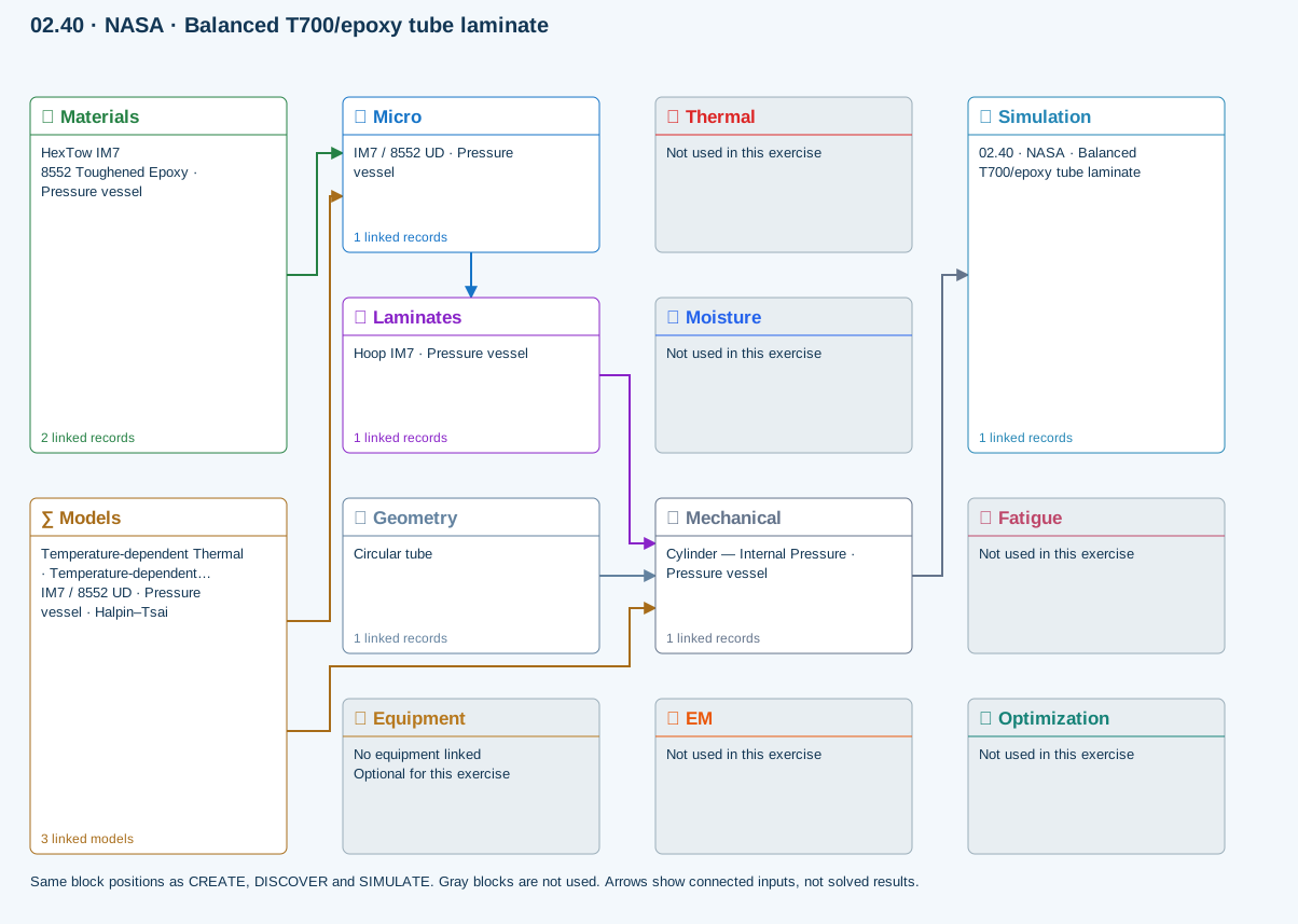
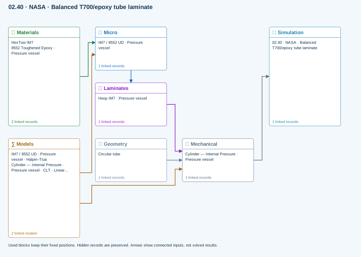
∑ Used models & submodels
Only models assigned to records used by this exercise are listed here. The full-layout option preserves the supplied starter records; no Workbench records are changed.
Halpin–Tsai · IM7 / 8552 UD · Pressure vessel
One compatible homogenization model per Micro recipe. Separate recipes compare models; their predictions are not blended.
∑ Theory & assumptionsCLT · Linear thin-wall membrane · Cylinder — Internal Pressure · Pressure vessel
Shared laminate stiffness drives this membrane/CLT path. Failure criteria are independent comparisons, not blended models. Fatigue is a separate assessment.
∑ Theory & assumptionsData travelling between blocks
Micro → Laminates
Predicted ply stiffness, strength, density and expansion properties.
Materials → Micro
Constituent stiffness, strength, density and thermal / moisture properties.
Mechanical → Simulation
SIMULATION selects this case and its analysis model; the case owns its applicable cycle and input references.
Laminates → Mechanical
Ply angles and thicknesses, stiffness, mass and ply properties.
Geometry → Mechanical
Part shape and dimensions, thickness or section definition, and model-specific geometric inputs. Each selected case consumes only the dimensions its model supports.
Models → Micro
Applied model assignment: Halpin–Tsai. Model parameters and formulation are used by Micro.
Models → Mechanical
Applied model assignment: CLT · Linear thin-wall membrane. Model parameters and formulation are used by Mechanical.
Reference validation · 2026-09-20
Not benchmark validated
No matched quantitative reference comparison completed for the full exercise.
Recorded baseline only—not a certification of the current database, edited inputs, or every output. Analytical agreement is not experimental material or failure validation.
Source validation, comparisons and tested inputs
Execution: Completed (not validation)
The copied IM7 pressure-vessel records are scaffolding. Replace the ply source and dimensions with the published T700/epoxy inputs; a pressure load is not an axial or torsional test.
- NASA/TM—2014-216635 — Engineered Polymer Composites Through Electrospun Nanofiber Coating of Fiber Tows ↗Tables 1–2, printed pages 11–12 / PDF pages 15–16. Published estimated ply inputs and CLPT tube properties, not qualified or experimentally validated strengths.
Tested inputs
Input SHA-256: 62f30905ca77e7a9ea034fc9ccd4f6a70c3df7f709fae5acfdd161ac19d43652
Solver source SHA-256: 21b57ba5585334998ad98a0b2bac916764c93739a20e81f92e8e37cd50006f4a
- Classical-laminate and first-ply screening. Manufacturing variation and qualification are excluded; the source describes estimated ply data.
Separate published-data fixture: Benchmark validated — published calculation
Separate source-matched stiffness fixture, NOT the unchanged IM7 starter. Only Ex, Gxy and νxy. No experimental or strength validation.
| Quantity | CDS | Reference | Error % | Tolerance (relative + absolute) | Result |
|---|---|---|---|---|---|
| Ex (GPa) | 27.71415 | 27.7 | 0.05108303 | 1% + 0.00002 GPa | Pass |
| Gxy (GPa) | 39.54424 | 39.6 | -0.1408081 | 1% + 0.00002 GPa | Pass |
| νxy (—) | 0.67558 | 0.68 | -0.65 | 1% + 0.00002 — | Pass |
- NASA/TM—2014-216635 — Engineered Polymer Composites Through Electrospun Nanofiber Coating of Fiber Tows ↗Tables 1–2, printed pages 11–12 / PDF pages 15–16. Published estimated ply inputs and CLPT tube properties, not qualified or experimentally validated strengths.
Fixture inputs
{
  "E1GPa": 153,
  "E2GPa": 10.5,
  "G12GPa": 8.27,
  "nu12": 0.3,
  "stack": "[45/-45]4",
  "thicknessMm": 2.345
}
Download source-validation results (JSON) · Full 138-exercise study
Reproduce the classical-laminate response of a balanced [±45]₄ T700/epoxy tube and use it as a controlled starting point for a design study.
CDS can reproduce the laminate constitutive and first-ply screening calculations. It does not reproduce manufacturing variation or certify the report’s estimated input properties.
Published basis
1 primary sourceStarting data
Enter in the displayed units| Variable | Value | How it is used |
|---|---|---|
| Ply E1 / E2 / G12 | 153 / 10.5 / 8.27 GPa | Orthotropic lamina elasticity |
| Ply ν12 | 0.30 | In-plane Poisson coupling |
| Xt / Xc | 2760 / 781 MPa | Longitudinal tension and compression |
| Yt / Yc / S | 76.5 / 233 / 89.6 MPa | Transverse and shear failure inputs |
| Layup | [+45/−45]₄ | Eight equal-thickness plies |
| Tube OD / ID | 52.95 / 48.26 mm | Nominal wall thickness and geometry |
Review checkpoints
Comparison, not certification| Result | Published reference | Interpretation |
|---|---|---|
| Axial modulus | 27.7 GPa | Published thin-wall CLPT estimate |
| Shear modulus | 39.6 GPa | Published [±45]₄ laminate estimate |
| Axial Poisson ratio | 0.68 | Large extension coupling expected for the angle-ply tube |
| Tension / compression / torsion | 179 MPa / 176 MPa / 290 MPa | Estimated laminate strengths, not qualified allowables |
138 exercises, examples and case studies → · Your CDS library: overview, manuals and database downloads →
Create the published T700/epoxy ply
Create a separate orthotropic lamina record using the estimated ply properties reported by NASA.
Step-by-step instructions · 3 steps
- Enter the elastic constants and five in-plane strength values from the table.
- Set the record status to Representative and attach the NASA report as its source.
- Keep out-of-plane and environmental terms incomplete unless a documented source is available.
Build the balanced tube laminate
Create eight plies in the sequence [45/−45]₄ with equal thickness.
Step-by-step instructions · 3 steps
- Use the published OD and ID to calculate the nominal wall thickness: (52.95 − 48.26)/2 = 2.345 mm.
- Set each of eight plies to approximately 0.2931 mm so the stack matches that nominal wall.
- Confirm the LiveStack shows four balanced ±45 pairs and that A16 and A26 are near zero.
Review effective laminate properties
Run the laminate calculation and compare the axial modulus, in-plane shear modulus and major Poisson ratio with the published CLPT estimates.
Step-by-step instructions · 3 steps
- Open the laminate Summary and export Ex, Gxy and νxy.
- Record the absolute and percentage differences from 27.7 GPa, 39.6 GPa and 0.68.
- Inspect whether the thickness convention or transverse shear treatment explains any discrepancy.
Explore the design space without changing the benchmark
Preserve the baseline, then use a duplicate for a carpet or optimization study.
Step-by-step instructions · 3 steps
- Sweep the ±45 family while holding ply count, material and total wall thickness fixed.
- Map axial modulus against shear modulus and display extrema.
- Save the baseline and the best candidate as separate snapshots so the NASA configuration remains available for comparison.
Run a first-ply screening check
Apply axial or torsional loading separately and compare the predicted onset with the report’s estimated laminate strengths.
Step-by-step instructions · 3 steps
- Select a failure criterion supported by the available in-plane allowables.
- Run axial tension, axial compression and torsion as separate cases.
- Use the reported 179 MPa tension, 176 MPa compression and 290 MPa shear only as study checkpoints.