
Ply stack
Set material references, angles and thicknesses. The stack defines laminate stiffness, mass and reference properties.
Workflow / 03.3 Laminates
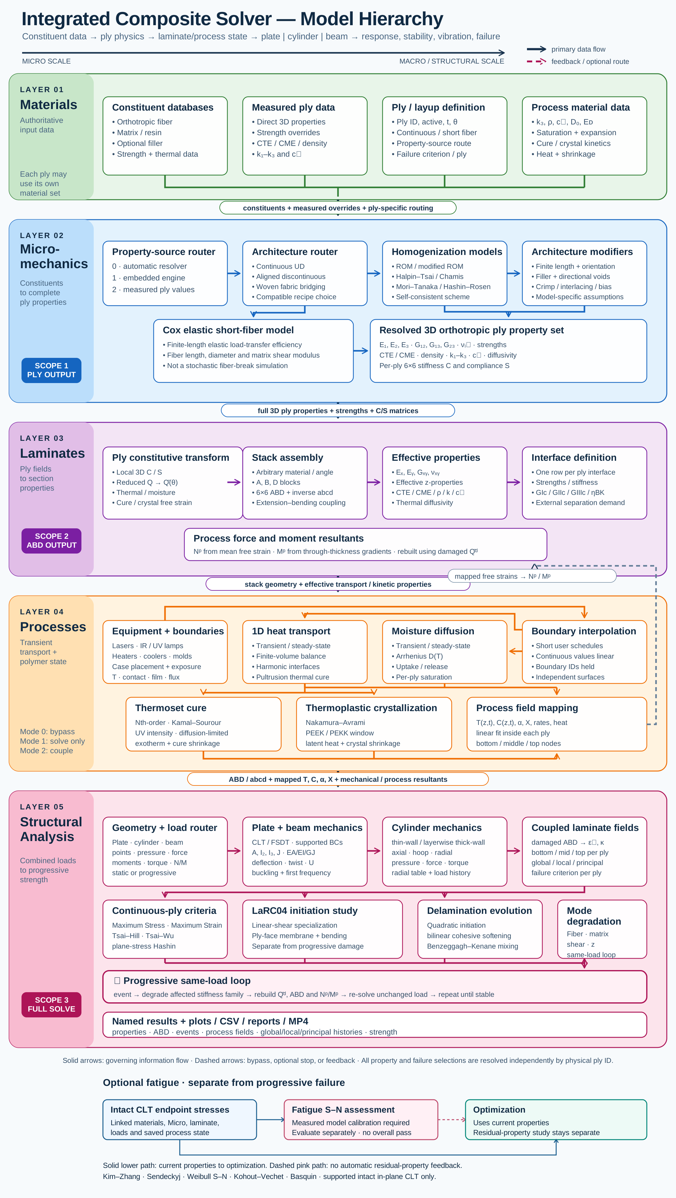
Connect stored or Micro-derived ply properties to a stacking sequence, then choose a compatible structural or separate analytical study.
Connected model layer
Select a block to explore its theory or workflow. View the complete Model Map
All blocks keep the CREATE / DISCOVER / SIMULATE positions, with Equipment below Geometry; unused records remain disconnected. This changes the view only, not the exercise records.
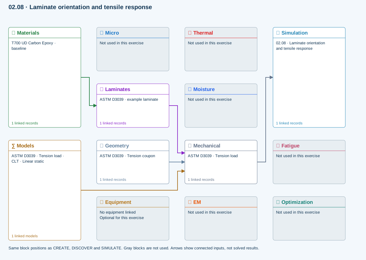
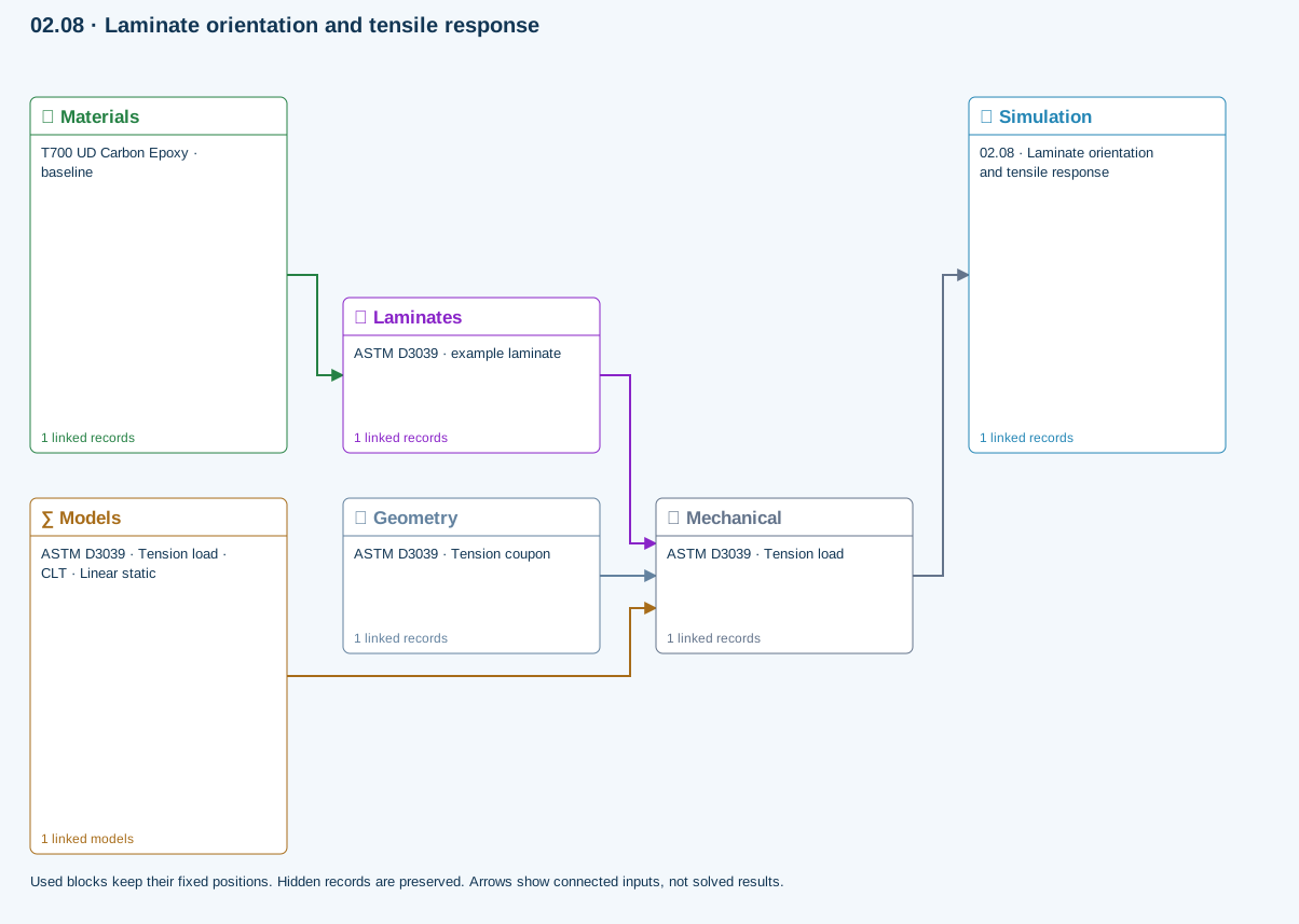
Only models assigned to records used by this exercise are listed here. The full-layout option preserves the supplied starter records; no Workbench records are changed.
Shared laminate stiffness drives this membrane/CLT path. Failure criteria are independent comparisons, not blended models. Fatigue is a separate assessment.
∑ Theory & assumptionsMaterials → Laminates
Stored ply stiffness, strength, density and expansion properties.
Mechanical → Simulation
SIMULATION selects this case and its analysis model; the case owns its applicable cycle and input references.
Laminates → Mechanical
Ply angles and thicknesses, stiffness, mass and ply properties.
Geometry → Mechanical
Part shape and dimensions, thickness or section definition, and model-specific geometric inputs. Each selected case consumes only the dimensions its model supports.
Models → Mechanical
Applied model assignment: CLT · Linear static. Model parameters and formulation are used by Mechanical.
Open the copied laminate and record the initial stacking sequence and total thickness.
Models: Classical laminate theory · Linear static · ASTM D3039-17(2025)-based
ASTM-based teaching geometry, not certification. Grips, tabs, alignment and physical test validity are not simulated.
03.3 / Workflow focus
Connected engineering recordSet material references, angles and thicknesses. The stack defines laminate stiffness, mass and reference properties.
ABD properties support laminate response. Finite-plate studies select CLT or FSDT within their supported boundary and study limits; static plate bending requires FSDT.
Eligible CLT cases use the released failure criteria. Coupled delamination belongs to the supported layerwise section path with calibrated interfaces, not every plate solver.
Open-hole strength, linear-shear LaRC04 initiation, axial creep and uncertainty use the linked laminate reference state. They do not automatically inherit process or progressive-damage histories.
Carpet maps and bounded optimization compare candidates. Apply a candidate and rerun the appropriate analysis; a saved result does not update itself.
Use this workflow in Workbench: interactive Blocks, record selections and connection controls →
Connected model layer
Select a model family to follow its inputs, results, theory and exercise. All model families ↗
Follow the connections
Laminate stiffness, finite plate dimensions, supported edges and study choice
FSDT static bending or selected buckling / modal results; not progressive damage
Representative exercise: this map shows its supplied records and active connections, not every possible configuration of the model family.
All blocks keep the CREATE / DISCOVER / SIMULATE positions, with Equipment below Geometry; unused records remain disconnected. This changes the view only, not the exercise records.
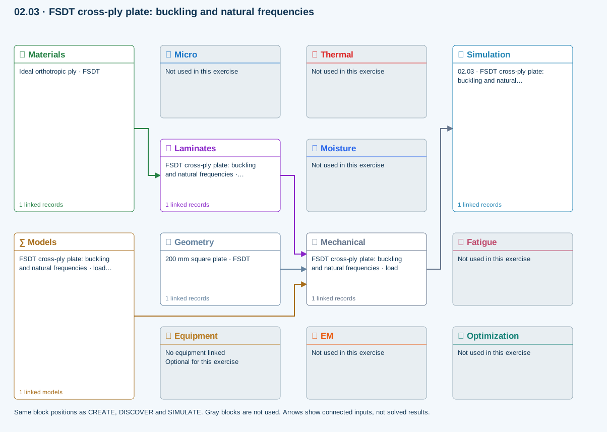
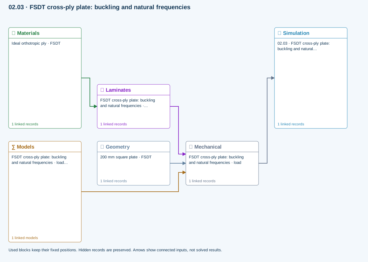
Choose a formulation and study. Buckling and modal can be requested together; static bending requires FSDT. These are reference-elastic studies, separate from coupled process or progressive failure.
Structural models → Laminate mechanics · CLT / FSDT