
Buckling and vibration are distinct analyses of the same structural system. This exercise helps you distinguish their inputs and outputs, while examining how laminate properties, transverse shear flexibility and numerical resolution affect the reported modes.
Open this exercise in Workbench
Prepare the baseline
Identify which study is active before each run. For buckling, record the reference load pattern to which the reported factor applies; for unprestressed vibration, remove the loads specified in the instructions. When comparing formulations or refinement levels, retain the same geometry and inspect mode shapes as well as the sorted numerical values.
Worked procedure
1. Open Simulation: check the shared skins/core, 1 / 18 / 1 mm stack, 300 × 200 mm Geometry, and paired Loading. Architecture must be Sandwich Structures; Automatic resolves to FSDT with Energy equivalent shear correction.
2. Run unprestressed modes with rotary inertia and compare the first three frequencies. Exchange core G13 and G23 and rerun to explore directional shear flexibility; compare shapes as well as sorted frequency order.
3. Increase Ritz order from 6 to 8; compare the quantity of interest before interpreting the result.
4. Select explicit CLT as a comparison, keeping all other inputs unchanged. Explain the difference due to transverse shear flexibility and rotary inertia.
Review checkpoints
Geometry owns length and width; Laminate owns skin/core thicknesses.
Static pressure and membrane loads are never combined in these examples. Modal loads are all zero.
Mode amplitudes are normalized, not physical vibration displacements. Density is explicit in skins and core.
Completion does not assess wrinkling, core crushing, debonding or delamination.
Model limits
Reference-elastic symmetric rectangular FSDT plate. Idealized teaching data, no calibrated material/strength claim. No thermal/moisture preload, thickness stretch, contact, debonding, damage or postbuckling. Directional energy-equivalent shear correction is an approximation; refine numerical order and compare published solutions.
Interpret the comparison
A buckling factor must be interpreted with its reference loads, whereas a frequency belongs to a particular vibration mode and unit system. Follow corresponding shapes when their ordering changes. Neither a linear buckling result nor a modal calculation establishes postbuckling strength or the response to an arbitrary dynamic load.
How information passes between models
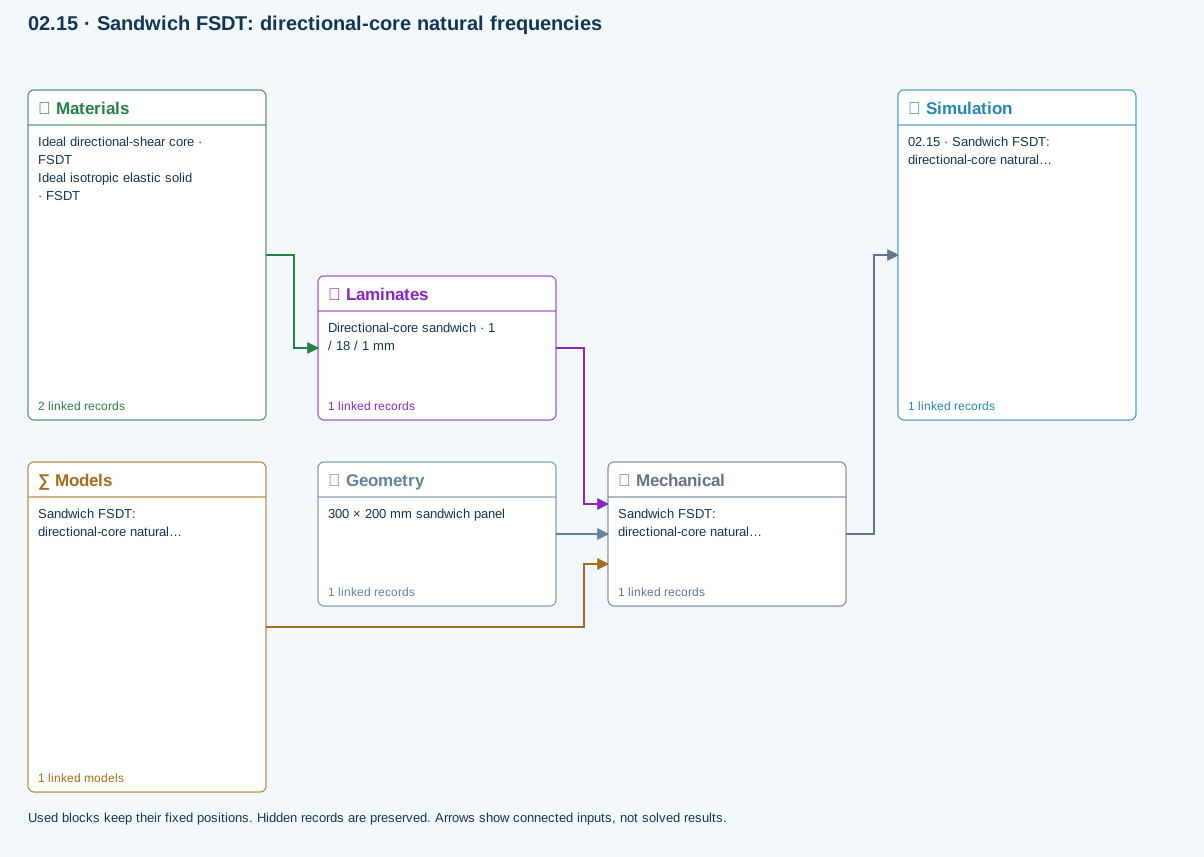
Materials → Laminates: Stored ply stiffness, strength, density and expansion properties.
Mechanical → Simulation: SIMULATION selects this case and its analysis model; the case owns its applicable cycle and input references.
Laminates → Mechanical: Ply angles and thicknesses, stiffness, mass and ply properties.
Geometry → Mechanical: Part shape and dimensions, thickness or section definition, and model-specific geometric inputs. Each selected case consumes only the dimensions its model supports.
Models → Mechanical: Applied model assignment: Automatic · Finite plate. Model parameters and formulation are used by Mechanical.
Further reading and evidence
- FSDT: shared laminate stiffness, shear and plate response
- Edit laminate materials, angles and thicknesses
- Run and review a model
- Geometry, loading and virtual tests
Review the recorded validation scope. Retain the original inputs and solver notices with the results. Representative teaching data are not design allowables.
References and source sections
References are retained with the formulations they support. Software instructions describe implementation scope; a cited source does not establish independent validation of a CDS calculation.