
A hybrid reinforcement introduces two changes that are easy to confuse: the amount of each fibre and the way the fibres are oriented. This exercise separates those effects so that you can explain the elastic response in terms of composition and architecture rather than attributing every change to the material names.
Open this exercise in Workbench
Prepare the baseline
First account for both fibre fractions, resin and voids, and confirm that they form a consistent composition. Complete the orientation comparison before redistributing volume between the two fibres. During the composition comparison, preserve total reinforcement so that changing fibre type is not also an unintended change in resin content.
Worked procedure
1. Inspect both linked fibers: 20% T700 plus 10% IM7, 2% voids and 68% resin. Rotate the live 3D view; normalized fiber lengths are illustrative only.
2. Run with Fa=1, then Fa=0/Fp=1, then Fa=0/Fp=0. Compare E1, E2, E3 and shear moduli.
3. Hold total fiber at 30% and move volume between fiber 1 and fiber 2. Rerun and compare stiffness and density.
4. Review classical failure inputs. The supplied zero allowables mean strength is not assessed; do not claim a pass from elasticity alone.
Review checkpoints
In-plane random orientation gives E1 = E2; spatial random orientation gives E1 = E2 = E3.
Fa=.5 and Fp=.5 represent 50% axial, 25% planar-random and 25% spatial-random fibers.
Cox transfer is evaluated per fiber modulus. Hybrid transverse closure is an averaged-constituent screening approximation; it does not model phase interaction or debonding.
Model limits
Prescribed orientation, common filament dimensions and resin. Voigt stiffness averaging; not a manufacturing orientation prediction or progressive failure model. Thermal transport retains aligned closure assumptions.
Interpret the comparison
Compare the complete directional stiffness response and density for each case. Explain which input changed between the runs and which remained fixed. The exercise’s absent or illustrative strength inputs must remain visible in your conclusion: a successfully calculated stiffness does not demonstrate that the hybrid meets a strength requirement.
How information passes between models
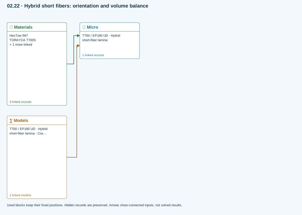
Materials → Micro: Constituent stiffness, strength, density and thermal / moisture properties.
Models → Micro: Applied model assignment: Cox shear-lag elastic. Model parameters and formulation are used by Micro.
Further reading and evidence
- Create and connect a lamina
- Edit material properties and units
- Run and review a model
- Review effective properties
- Connected inputs and result freshness
- Edit laminate materials, angles and thicknesses
- Related case study: NASA lamina analysis
Review the recorded validation scope. Retain the original inputs and solver notices with the results. Representative teaching data are not design allowables.
References and source sections
References are retained with the formulations they support. Software instructions describe implementation scope; a cited source does not establish independent validation of a CDS calculation.