Connect laminate behavior to structural performance.
Connect laminate mechanics to structural studies and the Virtual Test Lab. Mount composite specimens, follow calculated force and displacement, and inspect the corresponding response.
Through-thickness stress plots distinguish ply-level component response. This capture illustrates the CLT view, not an FSDT benchmark.
Workbench capture · September 6, 2026. Representative interface and demo data, not a new solver run or validation certificate. Control locations may differ in later releases.
Which load direction governs?
First-ply initiation envelopes compare five criteria in a mechanical-only teaching case. Sampled rays are not a converged design envelope.
What happens after first-ply failure?
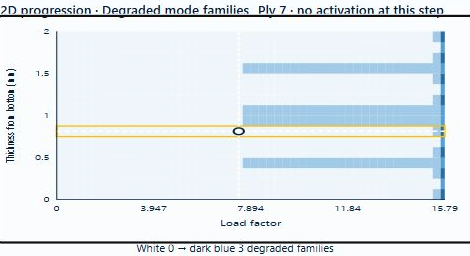
Progressive ramp with maximum-stress initiation and teaching retained-property defaults. Load factor is not time; these strengths are not qualified allowables.
02.6 / How CDS solves it
From engineering question to validation data
01
Virtual composite testing
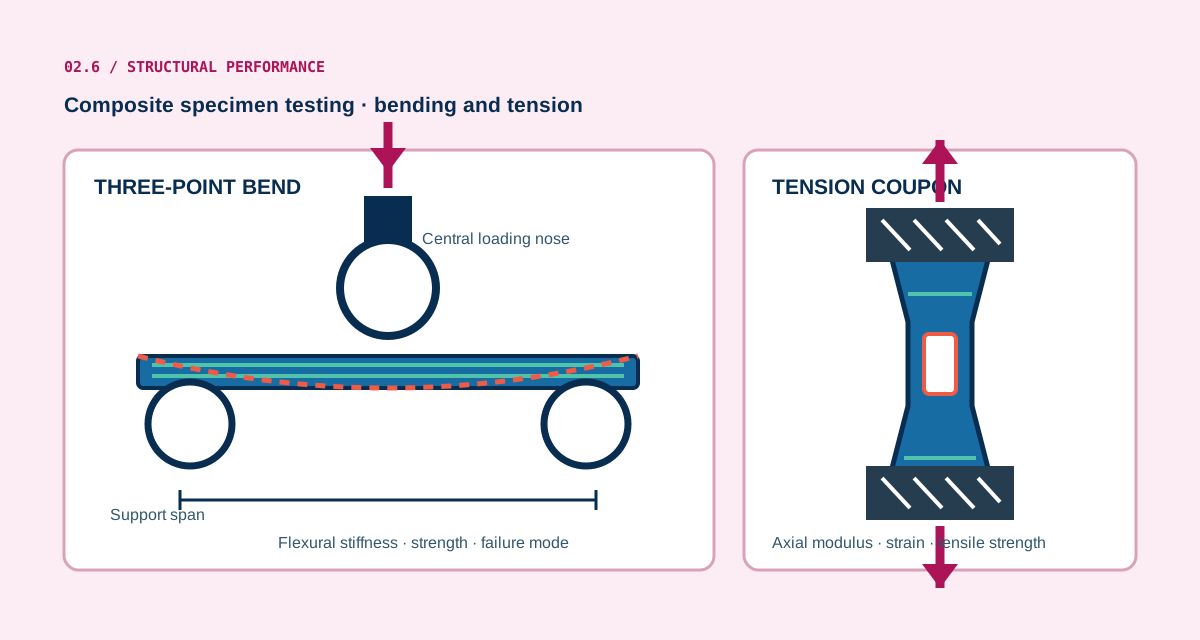
Use the mounted specimen and connected equipment with virtual instrument playback. ASTM D3039-based tension and D7264-based flexure provide guided entry points; axial coupon playback connects eligible progressive-failure results.
02
Plate and beam response
Use the released CLT/FSDT finite-plate or membrane/beam path with compatible dimensions, loads and supports. Buckling, modal and static bending are distinct study choices.
03
Cylinder formulations
Thin-wall membrane and layerwise thick-wall elasticity have different load and process limits. Donnell axial buckling is a separate thin-shell study with an explicit knockdown factor.
04
Sections and joints
Layerwise sections, lap joints and sandwich bending have their own geometry and interfaces. The analytical Volkersen / Goland–Reissner study is a separate identical-adherend elastic approximation.
05
Failure and notches
The five existing criteria support eligible CLT first-ply / progressive calculations. LaRC04 linear-shear initiation and calibrated open-hole strength are separate studies, not additional progressive choices.
06
Fatigue
S–N models predict life from calibrated data. Residual stiffness / strength requires independently fitted retention laws in its separate study; neither automatically changes optimization properties.
07
Creep, shape and uncertainty
Reference-state studies explore time response, prescribed-eigenstrain free release and bounded ABD sampling. Their scope, inputs and output handoffs are listed below.
08
Keep validation data connected
Run the selected Simulation after relevant edits. Review model assumptions, stale-result warnings, convergence and calibration before interpreting the result.
Compatibility and model licensing are checked for the selected Simulation.
Finite-plate, thick-wall cylinder and reference-state analytical studies have distinct assumptions.
Impact, ballistic tile and general 3D finite-element solves are not offered in the hosted release.
Teaching inputs and software checks do not establish experimentally qualified allowables.
Wing skins, spars, and ribs plus a wound composite tube represent plate, pressure, torsion, and axial-load analyses.Controls and workflow details · 6 features
Plate CLT/FSDT, membrane/beam and Euler studies
Thin-wall and layerwise cylinder models; separate Donnell buckling
Layerwise sections, lap joints, sandwich bending and supported cohesive growth
Five existing criteria, separate LaRC04 initiation and open-hole strength
Calibrated S–N and separate residual-property fatigue
Axial creep / relaxation, prescribed-eigenstrain tool release and bounded uncertainty