
The response calculation adds geometry, supports and loading to the material description. Check compatibility before interpreting an output and keep the baseline unchanged during comparison. CREATE and DISCOVER can organize candidate designs, but the final interpretation depends on the equations and constraints evaluated for those candidates.
6.1 Evaluate the complete composite structure.
Workflow / 03.5 Design
Choose a compatible released plate, cylinder, beam, section, joint or analytical study. Shared laminate inputs do not make every model combination valid.
Connected model layer
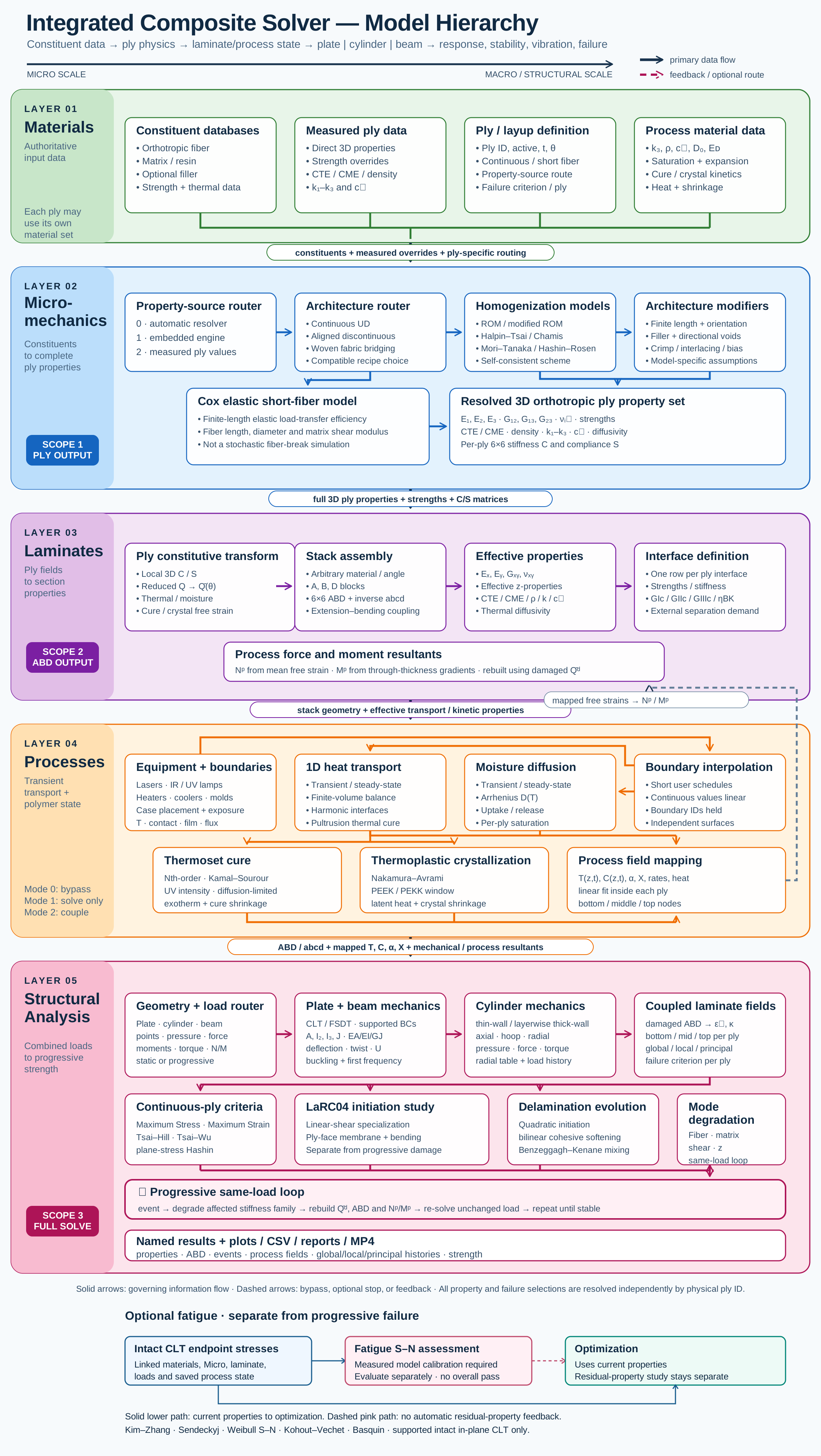
Structural analysis and design model map
Select a block to explore its theory or workflow. View the complete Model Map
Workbench path
Choose. Inspect. Refine.
Select the case
Choose a simulation block and the run you want to study.
Inspect in Live Sim
See geometry, assignments and results together.
Refine the model
Change geometry or selections and follow the downstream effect.
02.10 · Three-point bending: span and stiffness
Level 3IntermediateEst. 25 min
Only blocks on the exercise path are shown. This changes the view only, not the exercise records.
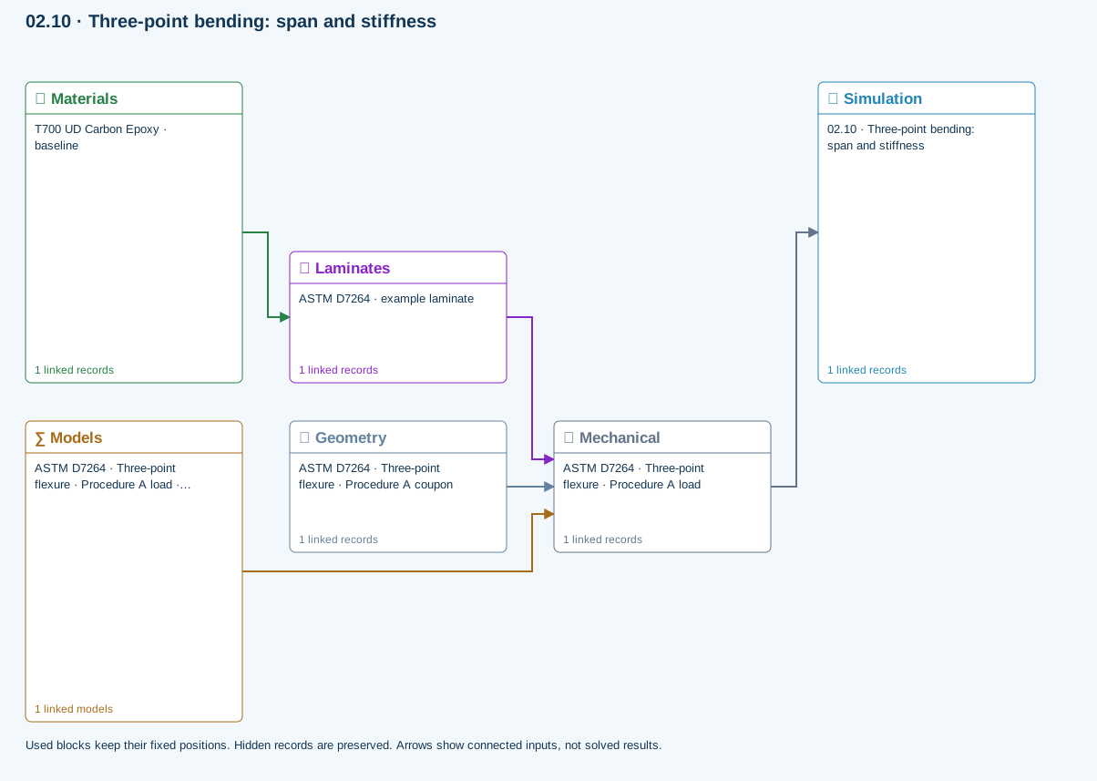
∑ Used models & submodels
Only models assigned to records used by this exercise are listed here. The full-layout option preserves the supplied starter records; no Workbench records are changed.
Euler–Bernoulli beam · Linear static · ASTM D7264 · Three-point flexure · Procedure A load
Beam bending uses effective laminate axial stiffness, the linked section geometry, support span and applied loading. Euler–Bernoulli deflection excludes transverse shear deformation, roller contact and indentation. Ply stress recovery for rectangular laminate coupons is separate from section-level beam stress recovery.
∑ Theory & assumptionsData travelling between blocks
Materials → Laminates
Stored ply stiffness, strength, density and expansion properties.
Mechanical → Simulation
SIMULATION selects this case and its analysis model; the case owns its applicable cycle and input references.
Laminates → Mechanical
Ply angles and thicknesses, stiffness, mass and ply properties.
Geometry → Mechanical
Part shape and dimensions, thickness or section definition, and model-specific geometric inputs. Each selected case consumes only the dimensions its model supports.
Models → Mechanical
Applied model assignment: Euler–Bernoulli beam · Linear static. Model parameters and formulation are used by Mechanical.
Inspect specimen width, laminate thickness, support span and central force.
Models: Euler–Bernoulli beam · ASTM D7264-based
Study scope and limitations
Procedure A teaching setup. Transverse shear deformation, roller contact and indentation are excluded.
03.5 / Workflow focus
Connected engineering recordPlate and beam response
Use the released CLT/FSDT finite-plate or membrane/beam path with compatible dimensions, loads and supports. Buckling, modal and static bending are distinct study choices.
Cylinder formulations
Thin-wall membrane and layerwise thick-wall elasticity have different load and process limits. Donnell axial buckling is a separate thin-shell study with an explicit knockdown factor.
Sections and joints
Layerwise sections, lap joints and sandwich bending have their own geometry and interfaces. The analytical Volkersen / Goland–Reissner study is a separate identical-adherend elastic approximation.
Failure and notches
The five existing criteria support eligible CLT first-ply / progressive calculations. LaRC04 linear-shear initiation and calibrated open-hole strength are separate studies, not additional progressive choices.
Fatigue
S–N models predict life from calibrated data. Residual stiffness / strength requires independently fitted retention laws in its separate study; neither automatically changes optimization properties.
Creep, shape and uncertainty
Reference-state studies explore time response, prescribed-eigenstrain free release and bounded ABD sampling. Their scope, inputs and output handoffs are listed below.
Keep validation data connected
Run the selected Simulation after relevant edits. Review model assumptions, stale-result warnings, convergence and calibration before interpreting the result.
Use this workflow in Workbench: interactive Blocks, record selections and connection controls →
Connected model layer
Design · released model connections
Select a model family to follow its inputs, results, theory and exercise. All model families ↗
Follow the connections
Heat, moisture & manufacturing
Material laws & boundary cycles
Roller radius, width, coating or metal properties, applied force and supported contact assumptions
Transport & reaction
History & compatible process fields
Contact footprint and pressure feeding applicable moving-process thermal and quality histories
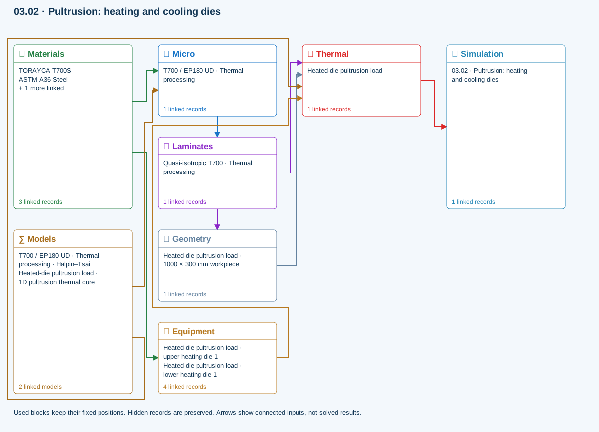
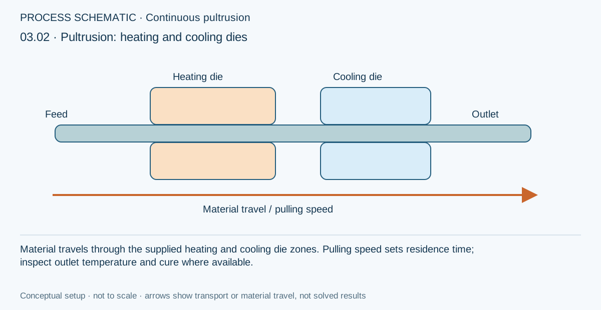
Thermal starting point: add roller Geometry and a roller boundary for a contact study; the supplied die exercise does not contain a roller.
Only blocks on the exercise path are shown. This changes the view only, not the exercise records.
Rubber-covered roller contact
Bonded coating on a rigid core against a rigid flat. Geometry selects Infinite width (analytical plane strain) or Finite width (3D elastic contact with axial end spreading). Small deformation and optional prescribed sliding friction; no hyperelasticity or rolling resistance.
Model choices and Workbench location
Geometry → Rollers; Models → Roller contact
- Bonded-layer roller contact
Chapter review
Use the same load and reference conventions when comparing alternatives, then rerun the selected design where required.
References and source sections
References are retained with the formulations they support. Software instructions describe implementation scope; a cited source does not establish independent validation of a CDS calculation.