
The workspace stores an engineering description as connected records. A material defines properties, while a laminate describes how those properties are arranged. A case adds the conditions under which the structure or process is evaluated. Learning these distinctions first makes the controls easier to understand: selecting a record changes what you inspect, whereas editing it can affect several dependent studies.
1.1 Explore the Workbench from model setup to results.
04 / Workbench guide
Choose a stage, inspect its Workbench view and follow the linked guide or exercise. Keep the input records and assumptions behind each result visible.
CREATE · DISCOVER · SIMULATE
Start learning: the CDS curriculum
Follow connected exercises from your first laminate to process, loading and structural studies. Choose a topic or model, then work through the setup, tasks and checkpoints.
Explore the complete curriculum →First time? Start here →Select a block to explore its inputs, results and theory. Run the engineering solvers in Workbench.
Materials
Traceable constituent properties
Start with source-aware elastic, strength, density and transport data. Teaching records help you explore; qualified design requires appropriate allowables.

Fatigue is optional and separate from progressive failure. An S–N life prediction is not a stiffness or strength reduction. Finite-plate CLT/FSDT and thick-wall cylinder studies have their own limits; they do not automatically include every process or failure model.
Explore this section
9 destinationsGetting Started
Sign in, open the Workbench, understand the project tree, and make your first safe GUI edit.
Workspace & Navigation
Learn the compact Project Manager tree, run controls, result views, editors, and live simulation summary.
Materials
Add, edit, duplicate, move, classify, lock, unlock, and delete material records.
Laminas & Laminates
Connect constituents, build ply stacks, review effective results, and create reusable materials from predictions.
Processes & Simulations
Solve steady-state or transient cases, include cure exotherm and cure-dependent modulus, optimize process cycles, preview LiveLoad vectors, and inspect result provenance.

Interface & Effective Use
Use responsive navigation, locally saved settings, scrollable tables, 2D/3D plot controls, exports, record actions, and local data tools efficiently.
Connected Workbench & Live Sync
Follow model dependencies, live and saved results, source-aware material records, grouped tree moves, multi-count duplication, boundary histories and comparison workflows.

Failure, Design Maps & Optimization
Set up failure envelopes and progressive analysis, explore 2D/3D carpet and microstructure maps, run laminate searches, save snapshots and compare studies.

Videos
Explore videos.
→1.2 Navigate the Workbench workspace.
04.2 / CDS User Guide
Understand the latest Project Manager, project tree, filters, record editor, and live connection summary.
06.1 Manuals · read online, preview or download →
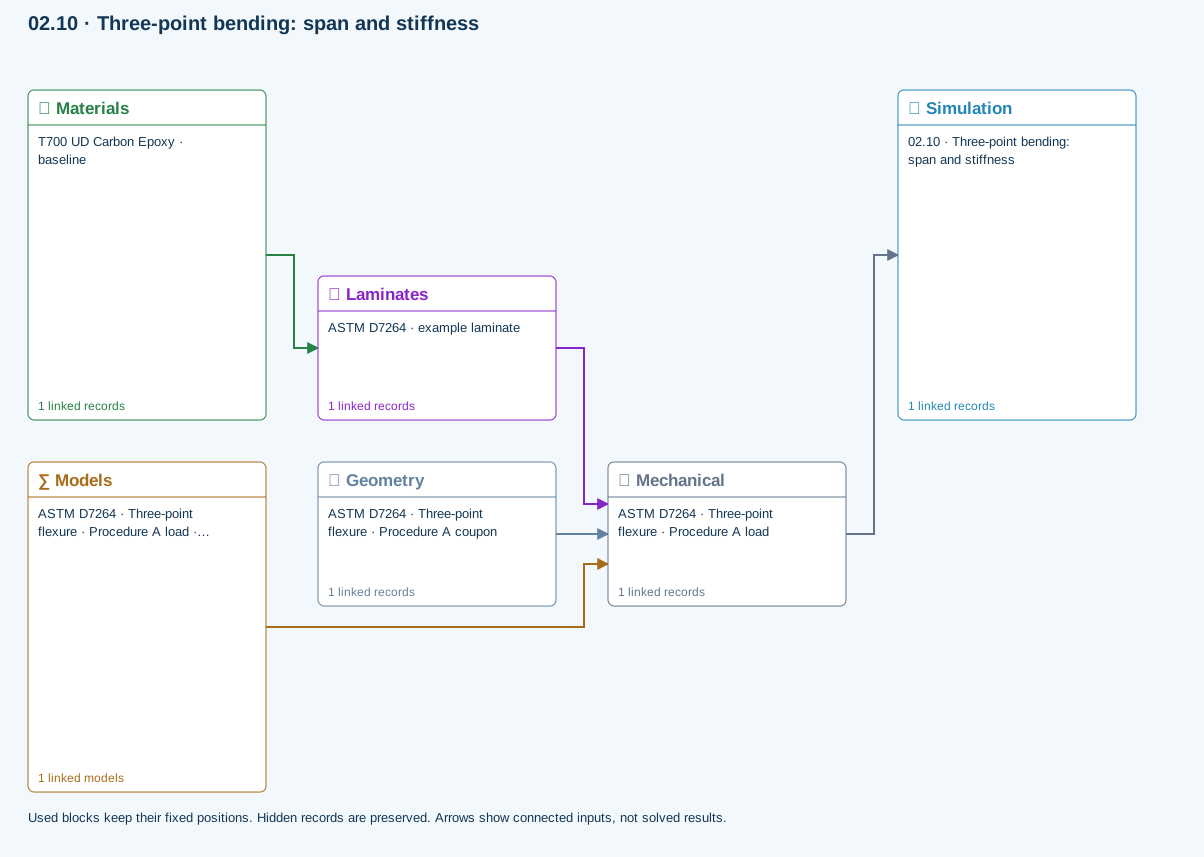
Explore the connected input path below. The dated GUI captures in the instructions show record controls; the current Simulation tab combines the earlier Solve and Summary views.
02.10 · Three-point bending: span and stiffness
Level 3IntermediateEst. 25 min
Only blocks on the exercise path are shown. This changes the view only, not the exercise records.
∑ Used models & submodels
Only models assigned to records used by this exercise are listed here. The full-layout option preserves the supplied starter records; no Workbench records are changed.
Euler–Bernoulli beam · Linear static · ASTM D7264 · Three-point flexure · Procedure A load
Beam bending uses effective laminate axial stiffness, the linked section geometry, support span and applied loading. Euler–Bernoulli deflection excludes transverse shear deformation, roller contact and indentation. Ply stress recovery for rectangular laminate coupons is separate from section-level beam stress recovery.
∑ Theory & assumptionsData travelling between blocks
Materials → Laminates
Stored ply stiffness, strength, density and expansion properties.
Mechanical → Simulation
SIMULATION selects this case and its analysis model; the case owns its applicable cycle and input references.
Laminates → Mechanical
Ply angles and thicknesses, stiffness, mass and ply properties.
Geometry → Mechanical
Part shape and dimensions, thickness or section definition, and model-specific geometric inputs. Each selected case consumes only the dimensions its model supports.
Models → Mechanical
Applied model assignment: Euler–Bernoulli beam · Linear static. Model parameters and formulation are used by Mechanical.
Inspect specimen width, laminate thickness, support span and central force.
Models: Euler–Bernoulli beam · ASTM D7264-based
Study scope and limitations
Procedure A teaching setup. Transverse shear deformation, roller contact and indentation are excluded.
Inspect the selected model in Live Sim
SIMULATE provides Simulation flow, Live view, Connections and Connected inputs tabs. Keep the active simulation selector visible while inspecting its fixed blocks or scene. Live views follow the selected simulation; they are input previews until a current solved history is available.
Step-by-step instructions · 4 steps
- Select Geometry, Laminate, a constituent or a case to inspect the inputs that are actually used. Clicking a used block heading also opens its Live Sim inspection.
- Select a ply in the stack or geometry view to inspect its source. Micro-derived and stored-property plies are identified separately. Woven sources show the fabric unit-cell preview when applicable.
- Select the Thermal or Moisture case to inspect its surface boundary schedule. Move the step slider to compare prescribed conditions. This is not a solved internal temperature or moisture field.
- Use Edit input to open the source record. The scene follows the changed inputs; rerun the simulation before trusting previous results.
Use the current CASES database format
This release reads and saves the current CASES database format only. Thermal and Moisture schedules are stored directly with their cases. There is no separate Process record or old-format migration on opening a file.
Step-by-step instructions · 3 steps
- Download a current starter or exercise database from the library. Older-format files are rejected with a clear message rather than converted silently.
- Save and reopen the current database to retain case selections, schedules, candidate records and editable names.
- Missing folders, duplicate identifiers and cycles attached to absent cases prevent saving or opening. Blank physical inputs remain editable and must be completed before Run.
Choose the run in the SIMULATION block
SIMULATION is the control point for the run. Select a Thermal case, Moisture case, Mechanical case and EM case, or None in any slot. Each selected case shows its analysis model, laminate and applicable geometry.
Step-by-step instructions · 4 steps
- Keep candidate records in the surrounding blocks. Adding a candidate does not select it for execution.
- Select the required cases in SIMULATION and review their inputs before Run. At least one case is required.
- Use the same laminate for a supported combined run. Run standalone studies separately with the other selectors set to None.
- Run executes the selected combination. A connection or Used marker is not confirmation of a successful solve.
Review every downstream geometry dependency
A geometry record can be shared by several cases and simulations. Editing its dimensions or type affects all linked consumers, including studies that are not currently open. Unrelated records are unchanged.
Step-by-step instructions · 4 steps
- After editing geometry, open Solver messages and expand Review affected cases and simulations. Select a linked name to inspect that record.
- Check the selected model, load basis, dimensions and boundary conditions. Loads are not automatically replaced when the geometry changes.
- Resolve incompatible geometry and model combinations before running. An I-section does not turn a plate theory into a beam theory.
- Rerun affected simulations before relying on previous results. Inputs changed warnings indicate that stored results no longer match their connected inputs.
Build the simulation from interactive blocks
Choose Block view above the left navigator for a vertical, editable workflow, or Blocks inside SIMULATE for the larger connection view. Live Sim inspects the selected model. Record dropdowns remain visible in Lite view.
Step-by-step instructions · 3 steps
- Choose the active simulation, then select compatible materials, Micro recipes, laminates, geometry and cases inside its blocks. Hybrid laminates can retain both stored-material and solved-Micro ply sources.
- Use the local Blocks Lite–Advanced switch for extra details without changing the rest of the workspace. Existing search and current-simulation filters still apply.
- Use the side connections to trace the input path. Hide connections or pause their animation locally; reduced-motion preferences are respected. Animation indicates connection direction, not solver progress.
Read the blue Used marker
Used markers identify consumed records. Availability and connection state do not require a green glow around a block. Hover or focus the marker to see which downstream record and field uses that input.
Step-by-step instructions · 3 steps
- Check the marker before editing a shared input: more than one case can consume it.
- A Used marker means connected, not solved or validated. Review solver status and outdated-result warnings separately.
- Missing or incompatible selections need repair; do not interpret an empty result as zero response.
Add, replace or disconnect a block input
The + control adds another available record to a block, excluding records already present. Use that record row dropdown to change the candidate, its link to open it, and − to remove it from the block. Library records are not deleted.
Step-by-step instructions · 4 steps
- Choose + and search for a compatible candidate not already in the block. Decide what actually runs with the four selectors in SIMULATION.
- If no compatible record exists, create one in Inputs. Each case owns its analysis model and applicable cycle. There is no separate Process block to connect.
- A used input must first be disconnected or changed at its consuming field. Review downstream warnings before confirming a removal; cancel to keep it.
- After removal, required missing inputs remain flagged and their selectors allow reconnection. Optional cases may stay disconnected. Rerun affected analyses before relying on their results.
Keep starter laminates in one classification
Generated Standard starter Conventional Laminates folders are consolidated into the main Conventional Laminates folder. Distinct laminate record IDs and their simulation links are preserved; identical titles alone are not a reason to delete a record.
Project Manager
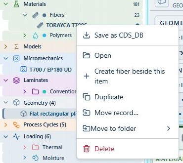
The Project Manager at the upper left combines navigation actions with the selected record’s context menu. Use it for create, open, save, load, export, and settings actions.
Step-by-step instructions · 4 steps
- Select a tree item first.
- Open Project Manager.
- Confirm the action scope: selected record, subtree, or entire database.
- Choose the required action.
Compact project tree
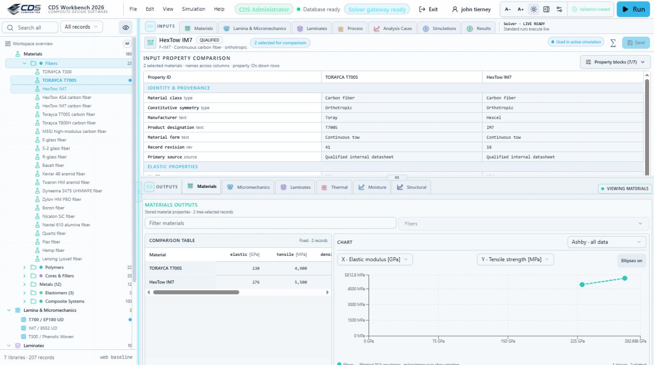
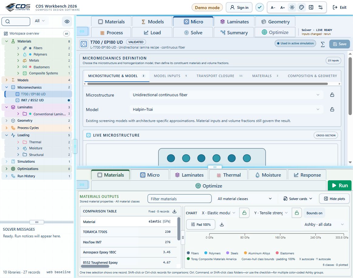
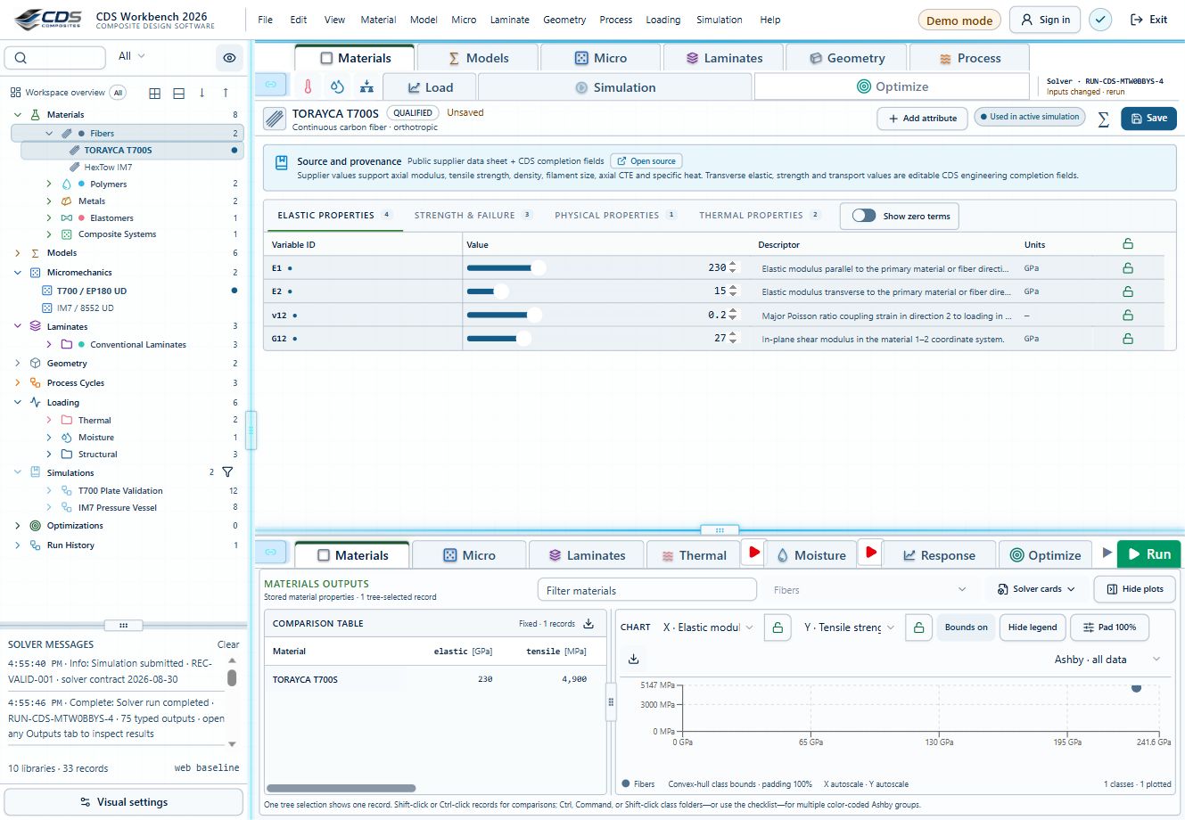
The left tree follows the engineering data chain: Materials, Models, Micromechanics, Laminates, Geometry, Equipment, CASES and Simulations. CASES contains Thermal, Moisture, Mechanical and EM records, each with its own applicable cycle. Click a folder label to select its child records, including nested children that match the current tree filters. Inputs and Outputs independently follow this multi-selection when their Live sync is on; a panel with Live sync off stays pinned. Ctrl-click adds or removes a folder’s records; Shift-click adds them. Use the chevron to expand or collapse without changing selection.
Search, filter, and visibility
Search locates records by title or descriptor. The All records dropdown and type filters narrow the visible records while preserving the primary tree. The eye control switches between the current simulation's records and all allowed records. Current simulation includes available candidates you added, even when they are not yet Used by the selected run.
Step-by-step instructions · 4 steps
- Enter a search term or choose a type filter. See screenshot
- Look for the blue active-filter treatment.
- Review Workspace filtered result.
- Clear search and filter to restore the full tree. See screenshot
Expand or collapse the tree
Workspace overview and its tree controls remain above the scrolling records. The open-book icon expands all; the closed-book icon collapses all. The arrows expand or collapse one level.
Selected record editor
Selecting an item opens its property editor. Compact tables show property names, descriptions, values, units and lock state. Predicted micromechanics and laminate properties remain read-only indicators; edit their connected source inputs instead.
Simulation workflow and scene controls
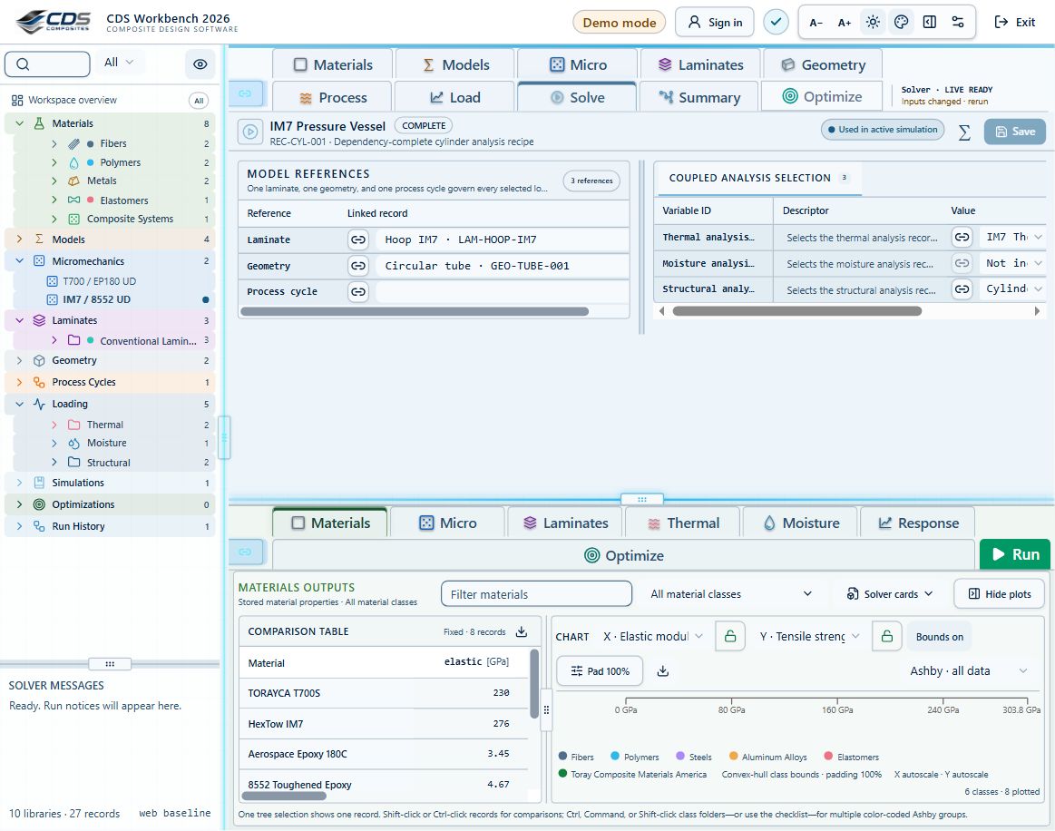
The Simulation tab combines the connected inputs and model workflow. Use the detail slider to move from the fixed high-level arrangement to model and field details. Zoom and pan the canvas around controls; block positions stay familiar. Select a record to inspect its inputs and use the controls inside a block to add, replace or disconnect records.
Step-by-step instructions · 4 steps
- Use the searchable simulation selector above the left tree to change the active case.
- Use the global Lite–Advanced switch for the workspace, or a local switch for one area.
- Inputs, Split and Outputs allocate pane space. Back and Forward revisit scenes, not previous data values.
- Use the visible Solver status to distinguish live updates, Run required and outdated results.
Results workspace
Materials, Micromechanics, and Laminates use the same four result views: Table, Ashby, Bar, and Line. The active tab is clearly highlighted. A single selected record shows its property view; multiple selected records use properties as rows and records as columns.
Chapter review
Before proceeding, identify the active record and the simulation that consumes it. Explain which information belongs to each rather than relying on the position of a block in the diagram.
References and source sections
References are retained with the formulations they support. Software instructions describe implementation scope; a cited source does not establish independent validation of a CDS calculation.