
Ply damage and interface separation are different mechanisms that may evolve during the same supported layerwise calculation. This exercise uses explicitly hypothetical inputs to teach you to read the accepted loading sequence and distinguish those mechanisms in the reported fields.
Open this exercise in Workbench
Prepare the baseline
Review the elastic, strength and cohesive inputs before running, retaining their illustrative status. Follow accepted increments rather than treating every displayed intermediate event as an equilibrium state. Compare the interface overlay with the ply-damage outputs at the same step, then repeat with the prescribed mesh and increment refinements.
Worked procedure
1. Review the explicitly hypothetical elastic, ply-strength and cohesive inputs. This is not a carbon material qualification.
2. Run; compare interface crack overlay, accepted-step timeline and ply damage.
3. Refine the mesh and load increments before interpreting crack-tip location or peak load.
Review checkpoints
The section contains two 1 mm layers and a 0.5 mm initial interface crack.
Both interface damage and ply damage are updated within the same equilibrium solution; thermal and moisture coupling are not included.
Model limits
Mechanical-only x-z reference-state demonstration coupling cohesive interfaces and in-plane ply damage. No thermal/moisture residual loading, out-of-plane ply failure or full 3D validation. Assumed teaching strengths and fracture energies; never a design certification.
Interpret the comparison
Discuss whether the location and progression of damage remain stable under refinement. A visually sharp crack overlay is not, by itself, evidence of a calibrated fracture prediction. Keep the assumed interface properties and the limits of the selected layerwise path alongside any peak-load or damage interpretation.
How information passes between models
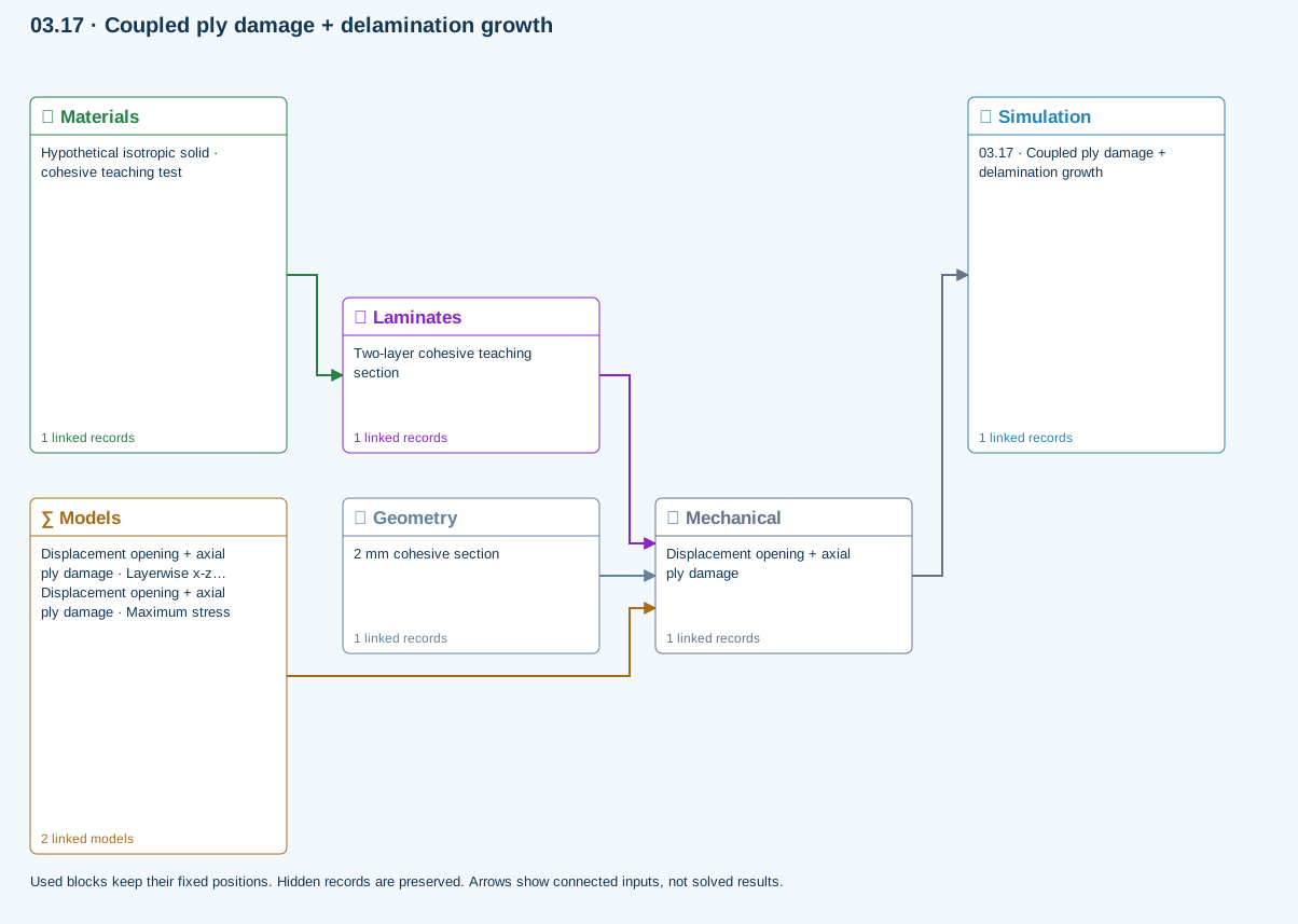
Materials → Laminates: Stored ply stiffness, strength, density and expansion properties.
Mechanical → Simulation: SIMULATION selects this case and its analysis model; the case owns its applicable cycle and input references.
Laminates → Mechanical: Ply angles and thicknesses, stiffness, mass and ply properties.
Geometry → Mechanical: Part shape and dimensions, thickness or section definition, and model-specific geometric inputs. Each selected case consumes only the dimensions its model supports.
Models → Mechanical: Applied model assignment: Layerwise x-z plane strain. Model parameters and formulation are used by Mechanical.; Maximum stress
Further reading and evidence
- Edit material properties and units
- Through-thickness section analysis and assumptions
- Run and review a model
- Connected inputs and result freshness
- Edit laminate materials, angles and thicknesses
Review the recorded validation scope. Retain the original inputs and solver notices with the results. Representative teaching data are not design allowables.
References and source sections
References are retained with the formulations they support. Software instructions describe implementation scope; a cited source does not establish independent validation of a CDS calculation.