
An environmental structural study is useful only if the temperature or moisture state used by the mechanical calculation is known. This exercise traces that handoff and compares the connected result with a deliberately controlled reference, so that changes in strain or ply stress can be attributed to the enabled contributions.
Open this exercise in Workbench
Prepare the baseline
Follow each selected case to the shared laminate, noting its own schedule and reference state. Record which cases are actually connected; some examples include moisture without thermal loading or use different resin systems in the same stack. Follow the specified disconnection procedure for the reference run and check that no separate mechanical process link remains active unintentionally.
Worked procedure
1. Trace alternating T700/epoxy and IM7/8552 Micro recipes and their 0.10/0.15 mm plies.
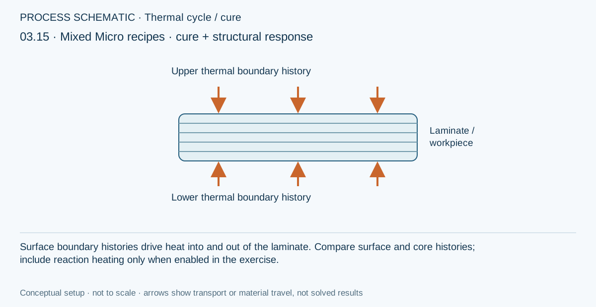
2. Run the shared thermal/structural simulation and inspect each resin cure history and the resulting structural state.
Review checkpoints
Moisture is deliberately disconnected.
The total thickness is 2 mm; both constituent systems contribute to the coupled calculation.
Model limits
Use the solver’s reported coupling state and limits. Do not assume this constitutes a general 3D coupled finite-element model or a calibrated cure-residual-stress prediction.
Interpret the comparison
Compare the transferred state as well as the mechanical outputs. Keep load, geometry and layup unchanged unless the task explicitly varies them, and explain whether the difference comes from free strain, state-dependent stiffness or another supported effect. Environmental exposure does not automatically imply strength degradation in every solver branch.
How information passes between models
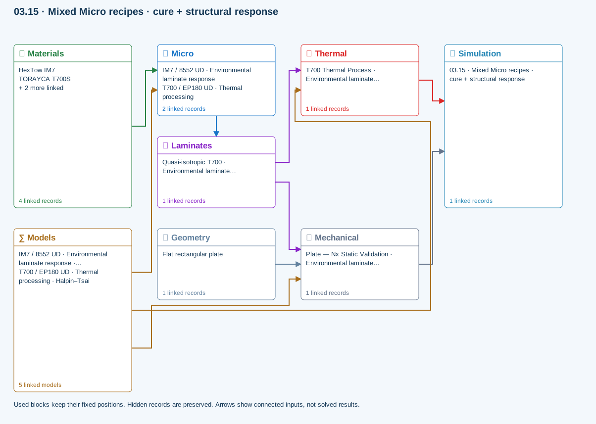
Micro → Laminates: Predicted ply stiffness, strength, density and expansion properties.
Materials → Micro: Constituent stiffness, strength, density and thermal / moisture properties.
Mechanical → Simulation: SIMULATION selects this case and its analysis model; the case owns its applicable cycle and input references.
Laminates → Mechanical: Ply angles and thicknesses, stiffness, mass and ply properties.
Geometry → Mechanical: Part shape and dimensions, thickness or section definition, and model-specific geometric inputs. Each selected case consumes only the dimensions its model supports.
Thermal → Simulation: SIMULATION selects this case and its analysis model; the case owns its applicable cycle and input references.
Laminates → Thermal: Ply angles and thicknesses, stiffness, mass and ply properties.
Models → Micro: Applied model assignment: Halpin–Tsai. Model parameters and formulation are used by Micro.; Halpin–Tsai
Models → Mechanical: Applied model assignment: CLT · Linear static with failure indices. Model parameters and formulation are used by Mechanical.; Maximum stress
Models → Thermal: Applied model assignment: 1D transient heat transfer. Model parameters and formulation are used by Thermal.
Further reading and evidence
- Connect a simulation
- Edit laminate materials, angles and thicknesses
- Run and review a model
- Connected inputs and result freshness
- Related case study: NASA process cure
Review the recorded validation scope. Retain the original inputs and solver notices with the results. Representative teaching data are not design allowables.
References and source sections
References are retained with the formulations they support. Software instructions describe implementation scope; a cited source does not establish independent validation of a CDS calculation.