
A finite plate calculation connects a laminate to dimensions, edge restraints and transverse loading. These exercises focus on reading that connection correctly and, where relevant, understanding the role of transverse shear flexibility in the response of a thick or soft-core panel.
Open this exercise in Workbench
Prepare the baseline
Confirm the selected plate formulation and its required shear properties before running. Record the actual support conditions, not just the panel dimensions. For comparisons, change the specified restraint, thickness or shear correction while preserving the remaining inputs, and review deflection alongside rotations and transverse shear outputs.
Worked procedure
1. Open Simulation: check the shared skins/core, 1 / 18 / 1 mm stack, 300 × 200 mm Geometry, and paired Loading. Architecture must be Sandwich Structures; Automatic resolves to FSDT with Energy equivalent shear correction.
2. Run uniform-pressure bending with all edges clamped. Compare peak deflection and Qx/Qy with the same panel set to Simply supported; record the restraint effect.
3. Increase Ritz order from 6 to 8; compare the quantity of interest before interpreting the result.
4. Double Plate pressure and verify that linear deflection doubles. Save an independent copy before changing shared records.
Review checkpoints
Geometry owns length and width; Laminate owns skin/core thicknesses.
Static pressure and membrane loads are never combined in these examples. Modal loads are all zero.
w is a physical displacement in mm; Qx/Qy are shear resultants, not interface stresses.
Completion does not assess wrinkling, core crushing, debonding or delamination.
Model limits
Reference-elastic symmetric rectangular FSDT plate. Idealized teaching data, no calibrated material/strength claim. No thermal/moisture preload, thickness stretch, contact, debonding, damage or postbuckling. Directional energy-equivalent shear correction is an approximation; refine numerical order and compare published solutions.
Interpret the comparison
Compare results only after checking numerical refinement. A change caused by a different support condition is a different effect from a change caused by shear modelling or solution order. Describe the quantity that converged and its units, rather than concluding that the whole analysis is accurate because the run completed.
How information passes between models
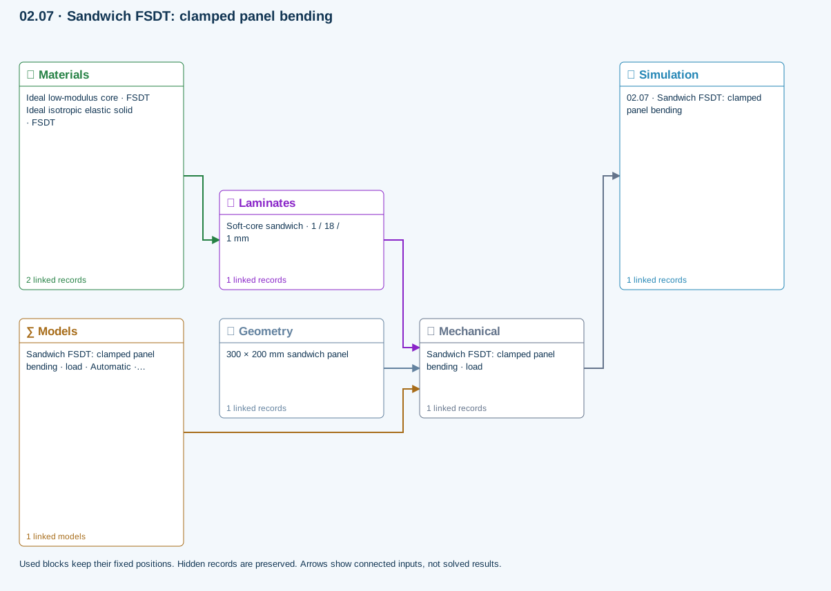
Materials → Laminates: Stored ply stiffness, strength, density and expansion properties.
Mechanical → Simulation: SIMULATION selects this case and its analysis model; the case owns its applicable cycle and input references.
Laminates → Mechanical: Ply angles and thicknesses, stiffness, mass and ply properties.
Geometry → Mechanical: Part shape and dimensions, thickness or section definition, and model-specific geometric inputs. Each selected case consumes only the dimensions its model supports.
Models → Mechanical: Applied model assignment: Automatic · Finite plate. Model parameters and formulation are used by Mechanical.
Further reading and evidence
- FSDT: shared laminate stiffness, shear and plate response
- Edit laminate materials, angles and thicknesses
- Run and review a model
- Geometry, loading and virtual tests
Review the recorded validation scope. Retain the original inputs and solver notices with the results. Representative teaching data are not design allowables.
References and source sections
References are retained with the formulations they support. Software instructions describe implementation scope; a cited source does not establish independent validation of a CDS calculation.