
A laminate can develop strain and curvature without an applied mechanical load when its layers respond differently to temperature, moisture or an enabled process strain. These exercises use controlled changes in stacking order, exposure or loading to distinguish that response from ordinary applied bending.
Open this exercise in Workbench
Prepare the baseline
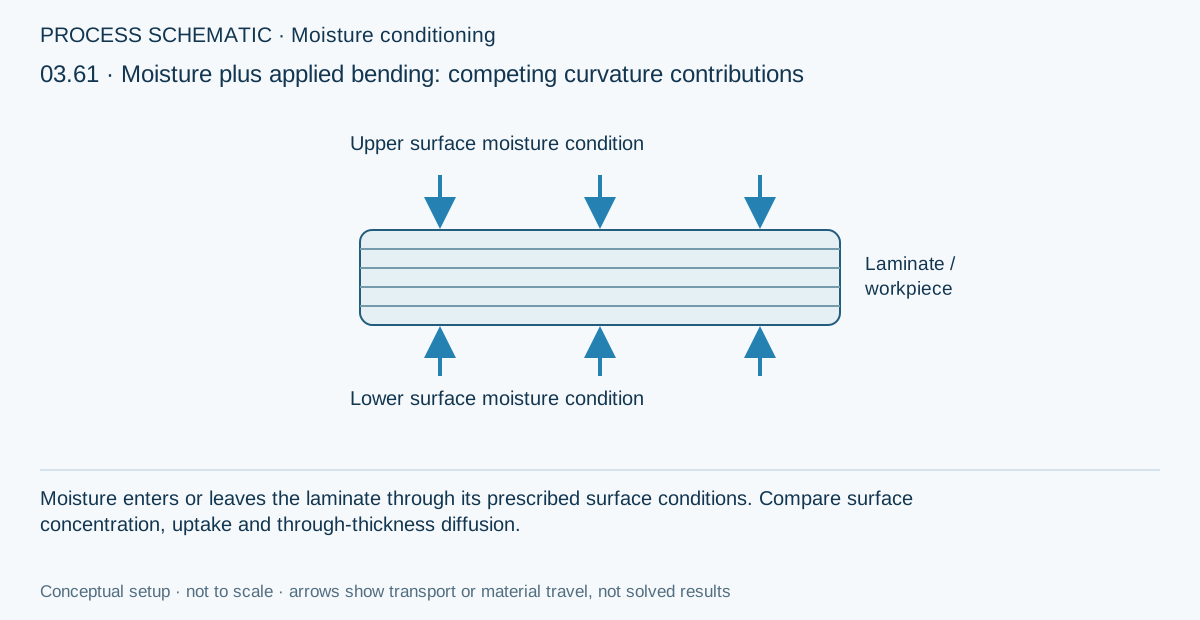
Inspect ply order, total thickness, reference states and applied loads before the baseline run. Record the environmental state actually consumed by the structural calculation. For a symmetric or reversed-stack comparison, preserve thickness and exposure as instructed; otherwise the change in curvature cannot be attributed to stacking order alone.
Worked procedure
1. Run the unsymmetric conditioned laminate with Nx = 25,000 N/m and Mx = 5 N per unit width.
2. Set applied loads to zero and rerun to isolate the environmental contribution.
3. Restore loads, reverse Mx to −5 N and rerun. Compare curvature and the most highly stressed plies.
4. Make a dry mechanical-only copy at the same loads and layup; distinguish environmental curvature from applied bending.
Review checkpoints
Moment resultant Mx is moment per unit width, with units N.
Opposing curvature contributions can reduce net deflection without eliminating local ply stress.
Model limits
Teaching inputs, not qualified allowables. Sequential coupling transfers the reported thermal/moisture state to laminate mechanics; it is not simultaneous 3D multiphysics. Inspect the transferred state and reference values before interpreting stress or curvature. No moisture-driven damage, swelling-dependent diffusion or experimentally calibrated strength degradation.
Interpret the comparison
Examine coupling terms and curvature together with ply stresses. Reversing a stack or removing applied loads is a diagnostic comparison, not a reason to assume every stress must disappear. If the exercise includes cure exotherm, distinguish the evolving process state from the final cooled state before calling a stress residual.
How information passes between models
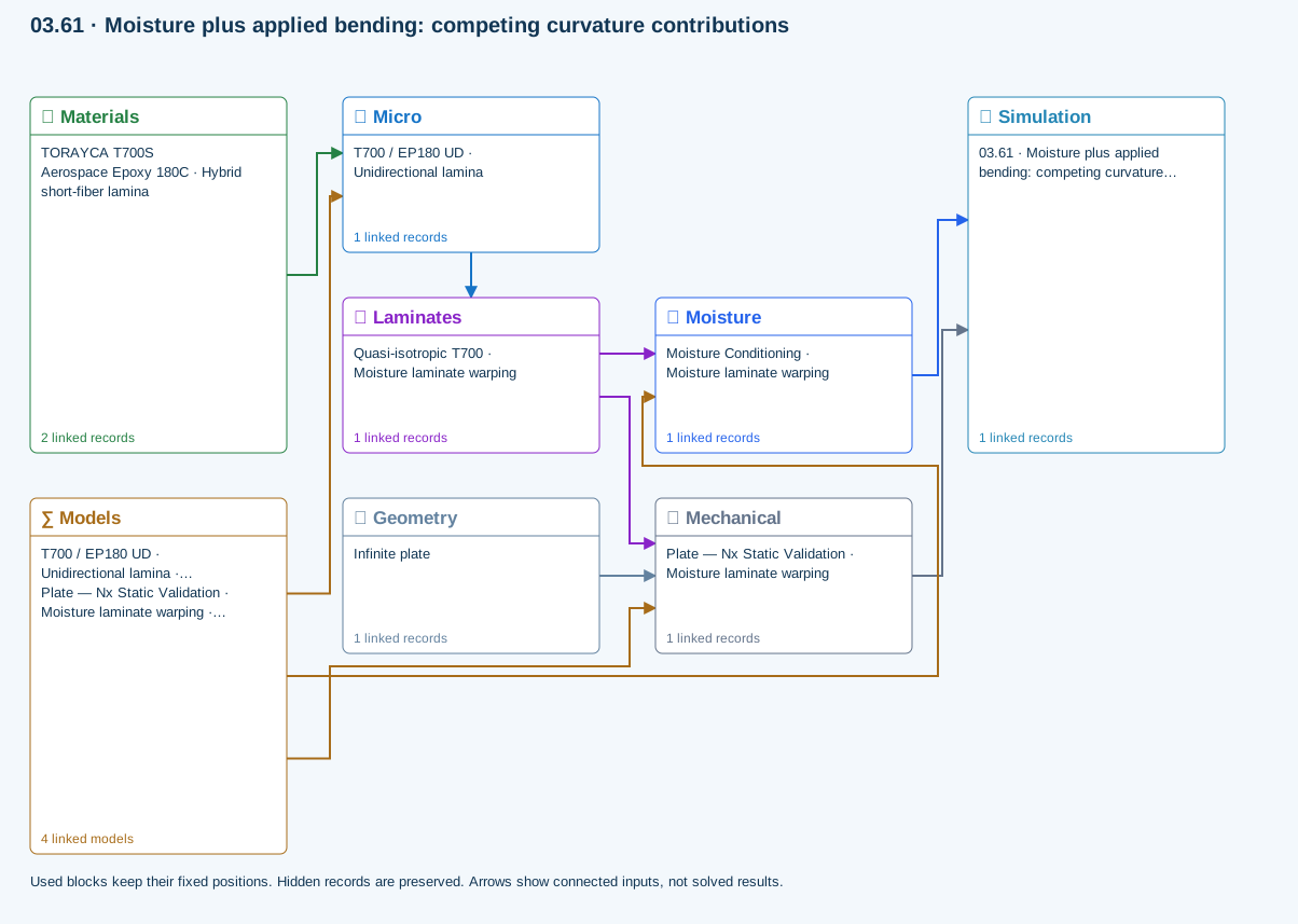
Micro → Laminates: Predicted ply stiffness, strength, density and expansion properties.
Materials → Micro: Constituent stiffness, strength, density and thermal / moisture properties.
Mechanical → Simulation: SIMULATION selects this case and its analysis model; the case owns its applicable cycle and input references.
Laminates → Mechanical: Ply angles and thicknesses, stiffness, mass and ply properties.
Geometry → Mechanical: Part shape and dimensions, thickness or section definition, and model-specific geometric inputs. Each selected case consumes only the dimensions its model supports.
Moisture → Simulation: SIMULATION selects this case and its analysis model; the case owns its applicable cycle and input references.
Laminates → Moisture: Ply angles and thicknesses, stiffness, mass and ply properties.
Models → Micro: Applied model assignment: Halpin–Tsai. Model parameters and formulation are used by Micro.
Models → Mechanical: Applied model assignment: CLT · Linear static with failure indices. Model parameters and formulation are used by Mechanical.; Maximum stress
Models → Moisture: Applied model assignment: 1D transient moisture diffusion. Model parameters and formulation are used by Moisture.
Further reading and evidence
- Connect a simulation
- Cure exotherm and evolving modulus
- Run and review a model
- Review effective properties
- Enter a process cycle and boundary conditions
- Edit laminate materials, angles and thicknesses
- Connected inputs and result freshness
- Apply symmetry and balance
- Related case study: NASA process cure
Review the recorded validation scope. Retain the original inputs and solver notices with the results. Representative teaching data are not design allowables.
References and source sections
References are retained with the formulations they support. Software instructions describe implementation scope; a cited source does not establish independent validation of a CDS calculation.