
UV exposure, local conversion, heating and stress describe different parts of the same illustrative study. This exercise helps you distinguish incident exposure from the state reached through the thickness, and identify how illumination, geometry and the chosen material laws affect that state.
Open this exercise in Workbench
Prepare the baseline
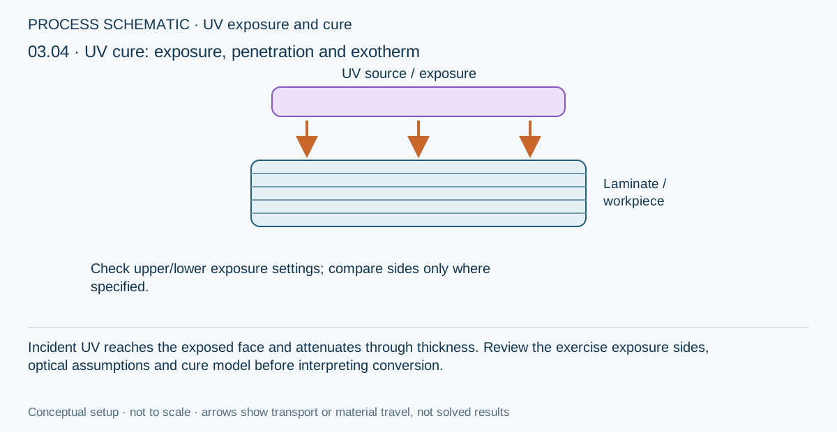
Inspect wavelength, optical inputs, exposure schedule and the hypothetical material calibration before running. Make the requested intensity, sidedness, duration or thickness comparison without changing the remaining inputs. When comparing equal incident doses, retain the full time history instead of assuming that dose alone determines the response.
Worked procedure
1. Trace the hypothetical matrix to its UV cure model and open the thermal case containing the 365 nm UV exposure cycle. Review the illustrative optical, kinetic and reaction-enthalpy inputs before running.
2. Run the supplied 60 s upper-surface exposure followed by cooling to 120 s. Compare intensity, dose, degree of cure, absorbed UV heating and reaction heating through thickness.
3. In Equipment, change the linked upper UV lamp surface irradiance from 1000 to 500 W/m²; rerun and compare surface/core cure. Restore 1000 W/m², then select a lower UV lamp at 1000 W/m² in Thermal UV settings to compare two-sided penetration. Exposure timing stays in the case.
4. Halve UV maximum time step from 0.1 to 0.05 s and increase thickness nodes. Check convergence and note that this model does not advance cure in the dark.
Review checkpoints
UV exposure timing is in seconds; the thermal boundary table is in minutes. Wavelength must match the linked UV model.
Low core conversion is an outcome to investigate, not a successful cure pass. Inspect depth profiles, not only surface cure.
Absorbed optical heating and resin reaction exotherm are separate heat sources; scattering loss is not converted to heat.
Model limits
Hypothetical UV-compatible teaching composite: inherited T700/epoxy elastic and transport values do not establish commercial resin UV compatibility or carbon-composite transparency. Effective optics, kinetics and enthalpy require calibration. No oxygen transport, shadowing, multiple scattering or radical dark cure. Use Run, not UV process optimization.
Interpret the comparison
Read the intensity and conversion profiles together with temperature and any enabled stress components. Compare final stresses at comparable cooled states, and inspect the gel and modulus evolution used by the model. Refine the stated time and thickness controls before interpreting small differences; the current model’s dark-cure limitation must remain part of the conclusion.
How information passes between models
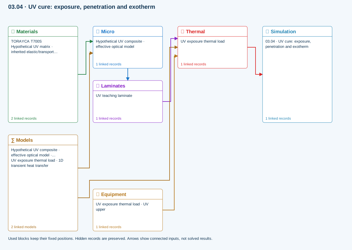
Micro → Laminates: Predicted ply stiffness, strength, density and expansion properties.
Materials → Micro: Constituent stiffness, strength, density and thermal / moisture properties.
Thermal → Simulation: SIMULATION selects this case and its analysis model; the case owns its applicable cycle and input references.
Laminates → Thermal: Ply angles and thicknesses, stiffness, mass and ply properties.
Equipment → Thermal: Linked lasers, IR/UV lamps, heaters, coolers and molds: dimensions, radiant power or prescribed temperature / heat flux, contact conductance, body and surface materials. Each boundary keeps its own placement, side and exposure.
Models → Micro: Applied model assignment: Halpin–Tsai. Model parameters and formulation are used by Micro.
Models → Thermal: Applied model assignment: 1D transient heat transfer. Model parameters and formulation are used by Thermal.
Further reading and evidence
- Connect a simulation
- Edit material properties and units
- Cure exotherm and evolving modulus
- Enter a process cycle and boundary conditions
- Run and review a model
- Connected inputs and result freshness
- Related case study: NASA process cure
Review the recorded validation scope. Retain the original inputs and solver notices with the results. Representative teaching data are not design allowables.
References and source sections
References are retained with the formulations they support. Software instructions describe implementation scope; a cited source does not establish independent validation of a CDS calculation.