
A result is useful only when its input state, numerical quality and interpretation can be recovered. Save the model selections, linked material values, geometry, boundary histories, numerical controls and software version with the output.
Start with dimensions and signs, then limiting cases, equilibrium and conservation. Test laminate symmetry and free-expansion limits. Refine mesh, integration step or candidate spacing until the decision-relevant output is sufficiently stable. State the convergence measure and tolerance rather than merely recording that a run completed.
Use measured geometry, conditioning, fixtures and loading when comparing against a test. Calibration adjusts model parameters; validation tests predictive use outside that fit. A virtual coupon implementing an analytical relation is not a physical standards-compliant test or certification.
Report quantities with units, coordinate conventions, reference states and meaningful precision. Include warnings and excluded physics. Separate calculated response, engineering interpretation and design acceptance. Exercises belong in the Training Manual and may illustrate a chapter, but they do not define the theory or establish design allowables.
10.1 13. Verification and Validation
13. Verification and Validation
Verification checks implementation consistency; validation establishes whether the calibrated model predicts the intended material and structure.
Core verification checks
- Source routing: linked and measured property sources must remain traceable independently for every ply.
- Symmetric quasi-isotropic laminates produce B≈0 and expected in-plane symmetry.
- Compatible Double-Double candidates preserve the stiffness objective within the reported error and substitute only ply angles when selected.
- Uniform free temperature/moisture expansion produces near-zero stress when unconstrained.
- Inert adiabatic transport conserves heat and insulated diffusion conserves moisture within numerical tolerance.
- Five-row top/bottom schedules interpolate to the requested transport grid while boundary types remain piecewise constant.
- Damaged thermal, moisture, process, and σz-Poisson resultants are rebuilt in every equilibrium pass.
- Failure uses mechanical strain; exports retain total, mechanical, thermal, moisture, and process-only contributions.
- Three nodes per active ply preserve linear in-plane gradients and compatible integrated w(z).
- Plate, shell/Hyer cylinder, and five beam-section routes return finite structural metadata and schema.
- Generated 6×6 compliance and stiffness matrices remain positive definite and reciprocal within tolerance.
Validation ladder
- Constituent and UD elastic, thermal, moisture, and transport tests.
- Tensile/compressive/shear strengths and strain allowables at relevant conditions.
- Multiaxial tests for interaction calibration, including F12*.
- DCB, ENF, and MMB data for cohesive parameters.
- Short-fiber RVE convergence and statistical repeatability.
- Laminate membrane and bending coupons, including conditioned hot/wet specimens.
- Representative structural details for final assessment.
10.2 Explore a test. Understand its limits.
ASTM / Virtual Test Lab
Ten connected analytical and measured-data studies, organized by familiar composite test families.
Find these in Workbench → Models → Structural models → ASTM · Virtual Test Lab, or filter exercises by ASTM. Each opens a separate connected SIMULATE study. Review the laminate, edit the test inputs, then Run or use live refresh where available.
Test-inspired, not ASTM certification. Defaults are hypothetical teaching values. The standards define physical test procedures; these bounded calculations do not reproduce every fixture, correction or validity requirement. Always consult the applicable current standard.
D6641 · Compression coupon
Uniform small-strain compression using linked laminate Ex and thickness. Measured compressive strength supplies a screening ratio; fixture, tabs, buckling and failure evolution are not simulated.
Equations, inputs and interpretation
σ = P/(wt), ε = σ/Ex, δ = εL.
Ex and total thickness come from the connected laminate. Stress, strain and force are positive compression magnitudes. The curve is elastic specimen shortening, not crosshead travel. Measured compressive strength is an independent input; the solver does not predict it from Ex. The small-strain limit is 2%.
- Specimen width (mm)
- Gauge length (mm)
- Applied force (N)
- Measured compressive strength (MPa)
Connected workflow
Only blocks on the exercise path are shown. This changes the view only, not the exercise records.
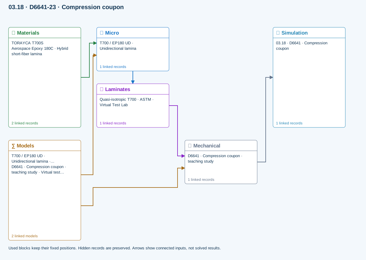
∑ Used models & submodels
Only models assigned to records used by this exercise are listed here. The full-layout option preserves the supplied starter records; no Workbench records are changed.
Halpin–Tsai · T700 / EP180 UD · Unidirectional lamina
One compatible homogenization model per Micro recipe. Separate recipes compare models; their predictions are not blended.
∑ Theory & assumptionsVirtual test · compression coupon · D6641 · Compression coupon · teaching study
Uniform small-strain compression using linked laminate Ex and thickness. Measured compressive strength supplies a screening ratio; fixture, tabs, buckling and failure evolution are not simulated.
Linked laminate reference state
Ply stiffness, thickness and orientation come from the linked laminate. Other thermal or structural analyses must be run separately.
Calibration & study controls
Teaching example
Specimen width: 25 mm
Gauge length: 25 mm
Applied force: 1000 N
Positive magnitude. Compression is reported as a magnitude.
Measured compressive strength: 400 MPa
Data travelling between blocks
Micro → Laminates
Predicted ply stiffness, strength, density and expansion properties.
Materials → Micro
Constituent stiffness, strength, density and thermal / moisture properties.
Mechanical → Simulation
SIMULATION selects this case and its analysis model; the case owns its applicable cycle and input references.
Laminates → Mechanical
Ply angles and thicknesses, stiffness, mass and ply properties.
Models → Micro
Applied model assignment: Halpin–Tsai. Model parameters and formulation are used by Micro.
Models → Mechanical
Applied model assignment: Virtual test · compression coupon. Model parameters and formulation are used by Mechanical.
D5379 / D7078 · Shear coupon
Uniform nominal shear between notches using linked laminate Gxy and thickness. Not a notch/fixture stress field or nonlinear shear solution. Gauge length is the effective shear deformation length, not crosshead travel.
Equations, inputs and interpretation
τ = P/(bnet t), γ = τ/Gxy, δ = γLg.
Gxy and thickness come from the connected laminate. This uniform nominal-field approximation does not resolve the V-notch or grip stresses. Lg is an effective shear gauge length, not fixture travel. Supply measured shear strength separately. Both D5379 and D7078 are represented only at this nominal-response level.
- Net section width (mm)
- Shear gauge length (mm)
- Applied force (N)
- Measured shear strength (MPa)
Connected workflow
Only blocks on the exercise path are shown. This changes the view only, not the exercise records.
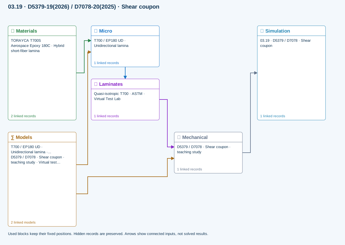
∑ Used models & submodels
Only models assigned to records used by this exercise are listed here. The full-layout option preserves the supplied starter records; no Workbench records are changed.
Halpin–Tsai · T700 / EP180 UD · Unidirectional lamina
One compatible homogenization model per Micro recipe. Separate recipes compare models; their predictions are not blended.
∑ Theory & assumptionsVirtual test · nominal shear coupon · D5379 / D7078 · Shear coupon · teaching study
Uniform nominal shear between notches using linked laminate Gxy and thickness. Not a notch/fixture stress field or nonlinear shear solution. Gauge length is the effective shear deformation length, not crosshead travel.
Linked laminate reference state
Ply stiffness, thickness and orientation come from the linked laminate. Other thermal or structural analyses must be run separately.
Calibration & study controls
Teaching example
Net section width: 12 mm
Shear gauge length: 10 mm
Applied force: 500 N
Measured shear strength: 80 MPa
Data travelling between blocks
Micro → Laminates
Predicted ply stiffness, strength, density and expansion properties.
Materials → Micro
Constituent stiffness, strength, density and thermal / moisture properties.
Mechanical → Simulation
SIMULATION selects this case and its analysis model; the case owns its applicable cycle and input references.
Laminates → Mechanical
Ply angles and thicknesses, stiffness, mass and ply properties.
Models → Micro
Applied model assignment: Halpin–Tsai. Model parameters and formulation are used by Micro.
Models → Mechanical
Applied model assignment: Virtual test · nominal shear coupon. Model parameters and formulation are used by Mechanical.
D5528 · DCB opening
Ideal Euler–Bernoulli DCB with equal homogeneous 0° arms, each half the linked laminate thickness. No root rotation, shear, large displacement or cohesive growth. Critical load is an initiation estimate from supplied GIc.
Equations, inputs and interpretation
C = 8a³/(Ebh³), GI = 12P²a²/(Eb²h³), Pc = √[GIc Eb²h³/(12a²)].
Each identical homogeneous 0° arm has thickness h = t/2. P is the force on each arm and δ = CP is relative opening. The linked ply E1 supplies the ideal beam modulus. Crack length stays fixed; Pc estimates initiation only. Root rotation, shear deformation, large deflection and compliance corrections required in experimental interpretation are absent. Use a/h ≥ 10.
- Specimen width (mm)
- Crack length (mm)
- Applied force (N)
- Critical fracture energy (N/mm)
Connected workflow
Only blocks on the exercise path are shown. This changes the view only, not the exercise records.
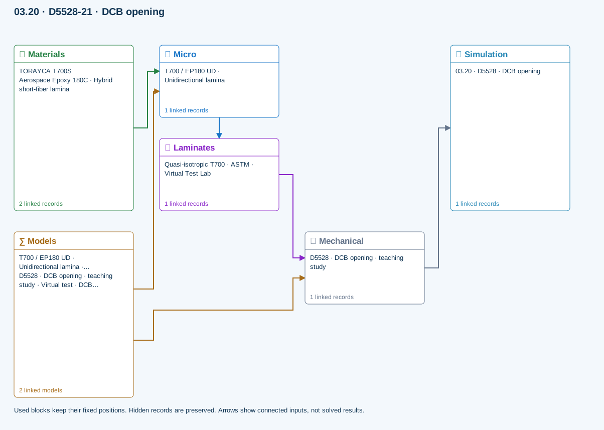
∑ Used models & submodels
Only models assigned to records used by this exercise are listed here. The full-layout option preserves the supplied starter records; no Workbench records are changed.
Halpin–Tsai · T700 / EP180 UD · Unidirectional lamina
One compatible homogenization model per Micro recipe. Separate recipes compare models; their predictions are not blended.
∑ Theory & assumptionsVirtual test · DCB beam compliance · D5528 · DCB opening · teaching study
Ideal Euler–Bernoulli DCB with equal homogeneous 0° arms, each half the linked laminate thickness. No root rotation, shear, large displacement or cohesive growth. Critical load is an initiation estimate from supplied GIc.
Linked laminate reference state
Ply stiffness, thickness and orientation come from the linked laminate. Other thermal or structural analyses must be run separately.
Calibration & study controls
Teaching example
Specimen width: 25 mm
Crack length: 30 mm
Applied force: 5 N
Critical fracture energy: 0.3 N/mm
Measured fracture energy; default is hypothetical.
Data travelling between blocks
Micro → Laminates
Predicted ply stiffness, strength, density and expansion properties.
Materials → Micro
Constituent stiffness, strength, density and thermal / moisture properties.
Mechanical → Simulation
SIMULATION selects this case and its analysis model; the case owns its applicable cycle and input references.
Laminates → Mechanical
Ply angles and thicknesses, stiffness, mass and ply properties.
Models → Micro
Applied model assignment: Halpin–Tsai. Model parameters and formulation are used by Micro.
Models → Mechanical
Applied model assignment: Virtual test · DCB beam compliance. Model parameters and formulation are used by Mechanical.
D7905 · ENF sliding
Ideal equal-arm, homogeneous 0° ENF beam; support span is twice the half-span. Crack must be shorter than the half-span. No shear/root correction or unstable crack growth. GIIc is supplied, not fitted automatically.
Equations, inputs and interpretation
C = (2L³ + 3a³)/(8Ebh³), GII = 9P²a²/(16Eb²h³).
L is the support HALF-span; each identical 0° arm has thickness h = t/2. The crack must satisfy a < L. At fixed crack length, δ = CP and the supplied GIIc determines the ideal initiation load. This is not an unstable crack-propagation simulation or a complete standard test reduction. Use slender beams.
- Specimen width (mm)
- Crack length (mm)
- Applied force (N)
- Critical fracture energy (N/mm)
- Support half-span (mm)
Connected workflow
Only blocks on the exercise path are shown. This changes the view only, not the exercise records.
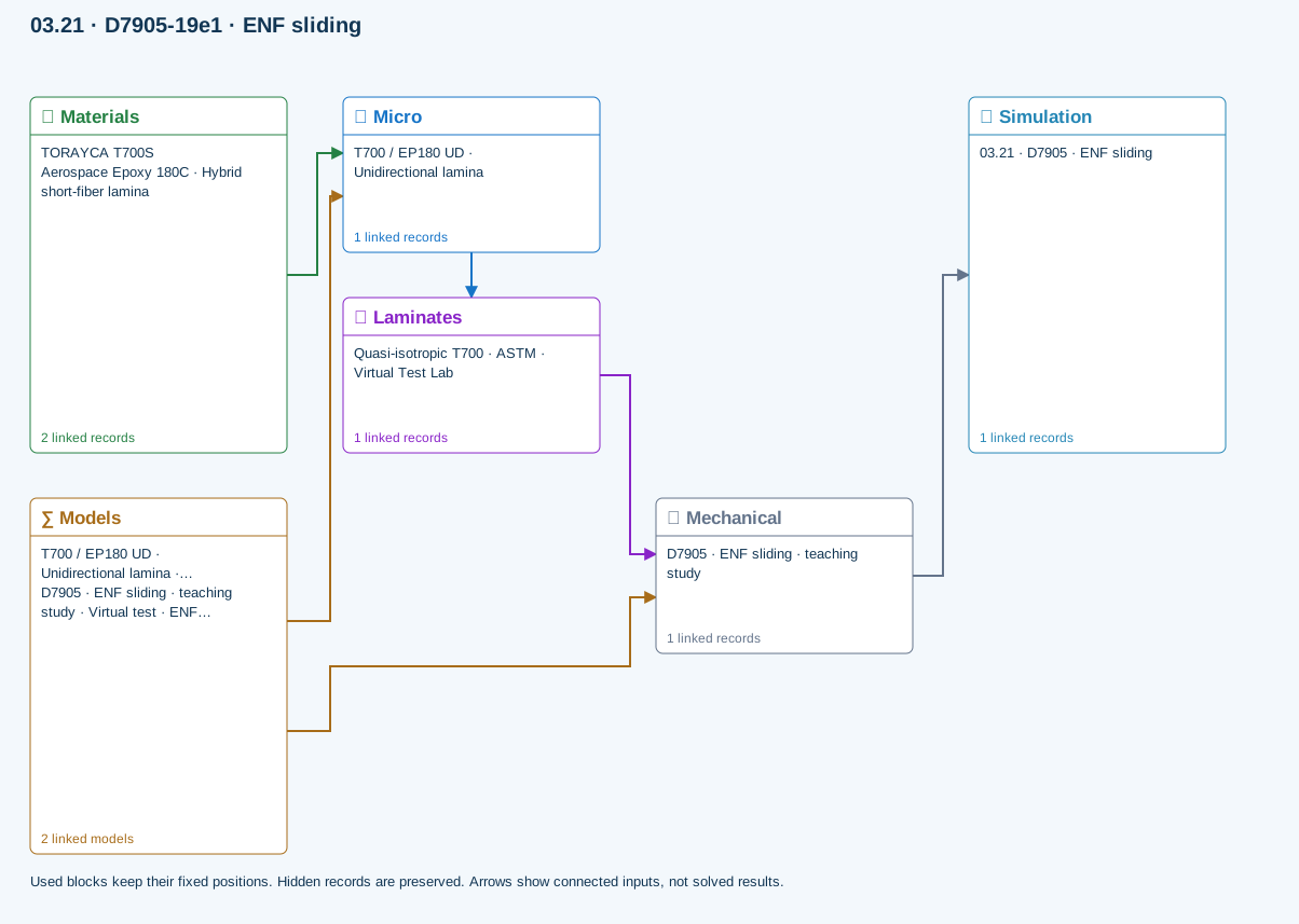
∑ Used models & submodels
Only models assigned to records used by this exercise are listed here. The full-layout option preserves the supplied starter records; no Workbench records are changed.
Halpin–Tsai · T700 / EP180 UD · Unidirectional lamina
One compatible homogenization model per Micro recipe. Separate recipes compare models; their predictions are not blended.
∑ Theory & assumptionsVirtual test · ENF beam compliance · D7905 · ENF sliding · teaching study
Ideal equal-arm, homogeneous 0° ENF beam; support span is twice the half-span. Crack must be shorter than the half-span. No shear/root correction or unstable crack growth. GIIc is supplied, not fitted automatically.
Linked laminate reference state
Ply stiffness, thickness and orientation come from the linked laminate. Other thermal or structural analyses must be run separately.
Calibration & study controls
Teaching example
Specimen width: 25 mm
Crack length: 30 mm
Applied force: 5 N
Critical fracture energy: 0.3 N/mm
Measured fracture energy; default is hypothetical.
Support half-span: 50 mm
Data travelling between blocks
Micro → Laminates
Predicted ply stiffness, strength, density and expansion properties.
Materials → Micro
Constituent stiffness, strength, density and thermal / moisture properties.
Mechanical → Simulation
SIMULATION selects this case and its analysis model; the case owns its applicable cycle and input references.
Laminates → Mechanical
Ply angles and thicknesses, stiffness, mass and ply properties.
Models → Micro
Applied model assignment: Halpin–Tsai. Model parameters and formulation are used by Micro.
Models → Mechanical
Applied model assignment: Virtual test · ENF beam compliance. Model parameters and formulation are used by Mechanical.
D6671 · Mixed-mode fracture envelope
Benzeggagh–Kenane envelope from calibrated GIc, GIIc and exponent. Supplied GI/GII are energy-release rates from a separate test reduction or analysis. This does not resolve the MMB lever fixture or propagate a crack.
Equations, inputs and interpretation
Gc = GIc + (GIIc − GIc) [GII/(GI + GII)]^η.
The BK envelope interpolates between measured pure-mode toughnesses using a calibrated exponent. The supplied GI and GII must come from an independent test reduction or compatible analysis. No lever-arm geometry or MMB fixture is solved. The laminate link keeps study provenance; laminate stiffness is not used to infer these energy-release rates.
- Mode I toughness (N/mm)
- Mode II toughness (N/mm)
- BK exponent (—)
- Applied GI (N/mm)
- Applied GII (N/mm)
Connected workflow
Only blocks on the exercise path are shown. This changes the view only, not the exercise records.
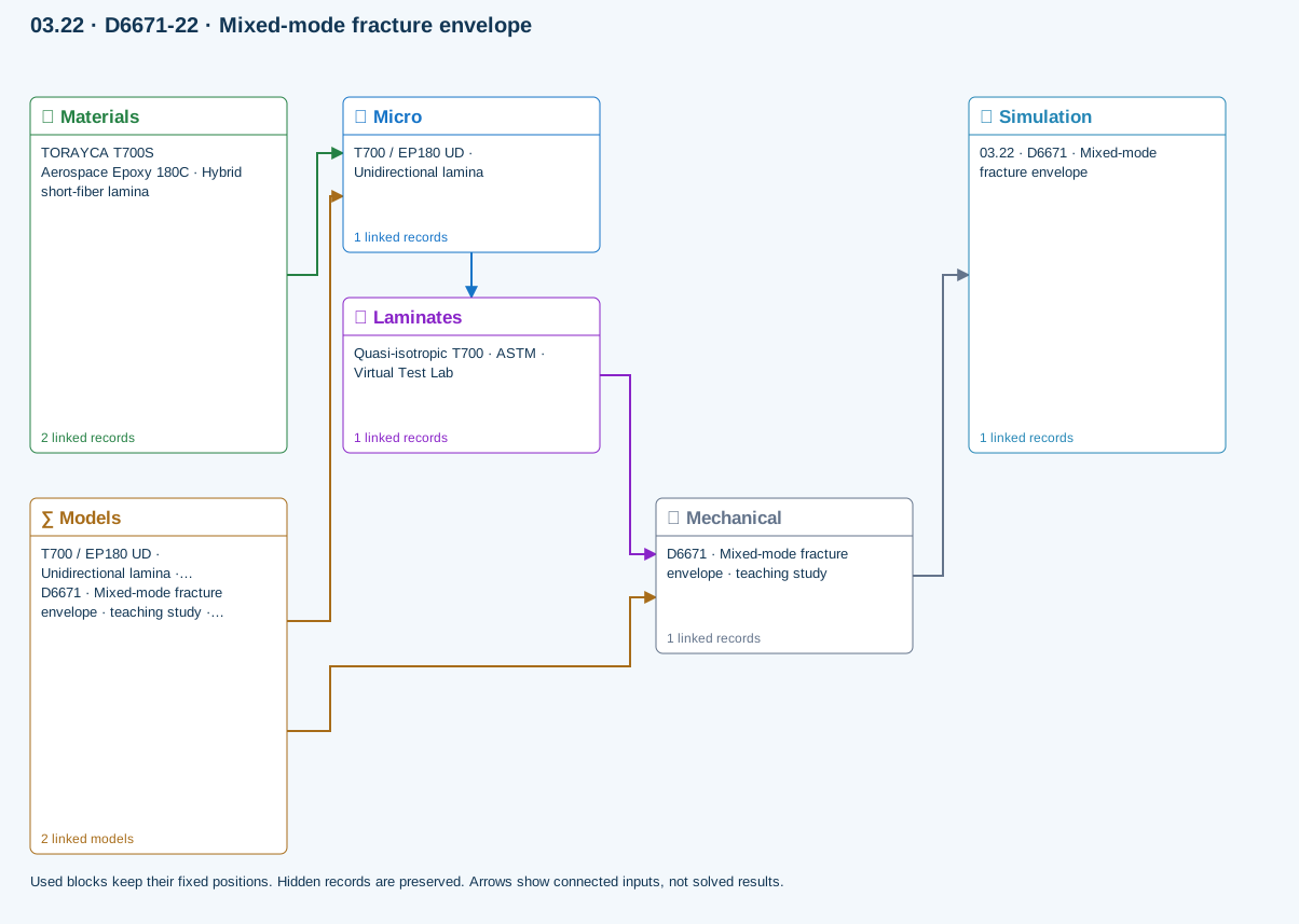
∑ Used models & submodels
Only models assigned to records used by this exercise are listed here. The full-layout option preserves the supplied starter records; no Workbench records are changed.
Halpin–Tsai · T700 / EP180 UD · Unidirectional lamina
One compatible homogenization model per Micro recipe. Separate recipes compare models; their predictions are not blended.
∑ Theory & assumptionsVirtual test · BK mixed-mode envelope · D6671 · Mixed-mode fracture envelope · teaching study
Benzeggagh–Kenane envelope from calibrated GIc, GIIc and exponent. Supplied GI/GII are energy-release rates from a separate test reduction or analysis. This does not resolve the MMB lever fixture or propagate a crack.
Linked laminate reference state
Ply stiffness, thickness and orientation come from the linked laminate. Other thermal or structural analyses must be run separately.
Calibration & study controls
Teaching example
Mode I toughness: 0.3 N/mm
Mode II toughness: 0.9 N/mm
BK exponent: 1.6 —
Applied GI: 0.1 N/mm
Applied GII: 0.2 N/mm
Data travelling between blocks
Micro → Laminates
Predicted ply stiffness, strength, density and expansion properties.
Materials → Micro
Constituent stiffness, strength, density and thermal / moisture properties.
Mechanical → Simulation
SIMULATION selects this case and its analysis model; the case owns its applicable cycle and input references.
Laminates → Mechanical
Ply angles and thicknesses, stiffness, mass and ply properties.
Models → Micro
Applied model assignment: Halpin–Tsai. Model parameters and formulation are used by Micro.
Models → Mechanical
Applied model assignment: Virtual test · BK mixed-mode envelope. Model parameters and formulation are used by Mechanical.
D5229 · Moisture uptake calibration
Homogeneous slab, initially dry, both faces held at equilibrium moisture. Fits diffusivity from two early uptake measurements (both ≤50% saturation) using the square-root-time approximation. Edge ingress and temperature dependence are excluded. Does not overwrite material properties.
Equations, inputs and interpretation
D = π [t × slope/(4M∞)]²; M(T)/M∞ = 1 − (8/π²) Σ exp[−(2j+1)²π²DT/t²]/(2j+1)².
Here t is total slab thickness and T is elapsed time. Two increasing early mass-gain points define slope = ΔM/Δ√T. Both must remain at or below 50% of equilibrium; an inconsistent dry intercept is rejected. The model assumes an initially dry homogeneous slab with both faces held at equilibrium, no edge ingress and constant diffusivity. D is reported in mm²/s. Copy it into a material only after independent validation; no saved material is changed. No temperature shifting or hot-wet strength degradation is inferred.
- Equilibrium mass gain (percent)
- Measurement time 1 (h)
- Mass gain 1 (percent)
- Measurement time 2 (h)
- Mass gain 2 (percent)
- Conditioning duration (h)
Connected workflow
Only blocks on the exercise path are shown. This changes the view only, not the exercise records.
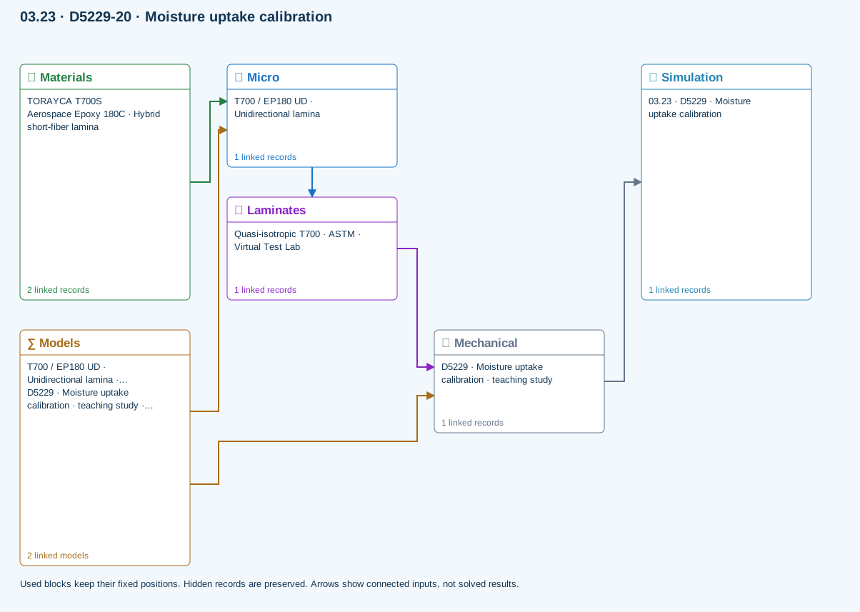
∑ Used models & submodels
Only models assigned to records used by this exercise are listed here. The full-layout option preserves the supplied starter records; no Workbench records are changed.
Halpin–Tsai · T700 / EP180 UD · Unidirectional lamina
One compatible homogenization model per Micro recipe. Separate recipes compare models; their predictions are not blended.
∑ Theory & assumptionsVirtual test · Fickian uptake calibration · D5229 · Moisture uptake calibration · teaching study
Homogeneous slab, initially dry, both faces held at equilibrium moisture. Fits diffusivity from two early uptake measurements (both ≤50% saturation) using the square-root-time approximation. Edge ingress and temperature dependence are excluded. Does not overwrite material properties.
Linked laminate reference state
Ply stiffness, thickness and orientation come from the linked laminate. Other thermal or structural analyses must be run separately.
Calibration & study controls
Teaching example
Equilibrium mass gain: 1 percent
Measurement time 1: 1 h
Mass gain 1: 0.05 percent
Measurement time 2: 4 h
Mass gain 2: 0.1 percent
Conditioning duration: 100 h
Data travelling between blocks
Micro → Laminates
Predicted ply stiffness, strength, density and expansion properties.
Materials → Micro
Constituent stiffness, strength, density and thermal / moisture properties.
Mechanical → Simulation
SIMULATION selects this case and its analysis model; the case owns its applicable cycle and input references.
Laminates → Mechanical
Ply angles and thicknesses, stiffness, mass and ply properties.
Models → Micro
Applied model assignment: Halpin–Tsai. Model parameters and formulation are used by Micro.
Models → Mechanical
Applied model assignment: Virtual test · Fickian uptake calibration. Model parameters and formulation are used by Mechanical.
D5961 · Bearing / bypass screening
Single-pin nominal bearing, net-section and shear-out checks with independent measured allowables. Bypass tension is added to net-section load only. No contact, bolt preload, load redistribution or validated bearing–bypass interaction envelope.
Equations, inputs and interpretation
σbearing = P/(dt); σnet = (P + Pbypass)/[(w − d)t]; τout = P/[2(e − d/2)t].
e is the hole-center distance to the loaded free edge. Each nominal stress is compared with its own measured allowable. Bypass tension contributes to the net-section load. These independent ratios are not a validated bearing–bypass interaction surface. Bolt preload, contact, friction, multi-fastener load sharing and progressive damage require further modeling.
- Specimen width (mm)
- Hole diameter (mm)
- Edge distance (mm)
- Pin force (N)
- Bypass tensile force (N)
- Bearing allowable (MPa)
- Net tensile allowable (MPa)
- Shear-out allowable (MPa)
Connected workflow
Only blocks on the exercise path are shown. This changes the view only, not the exercise records.
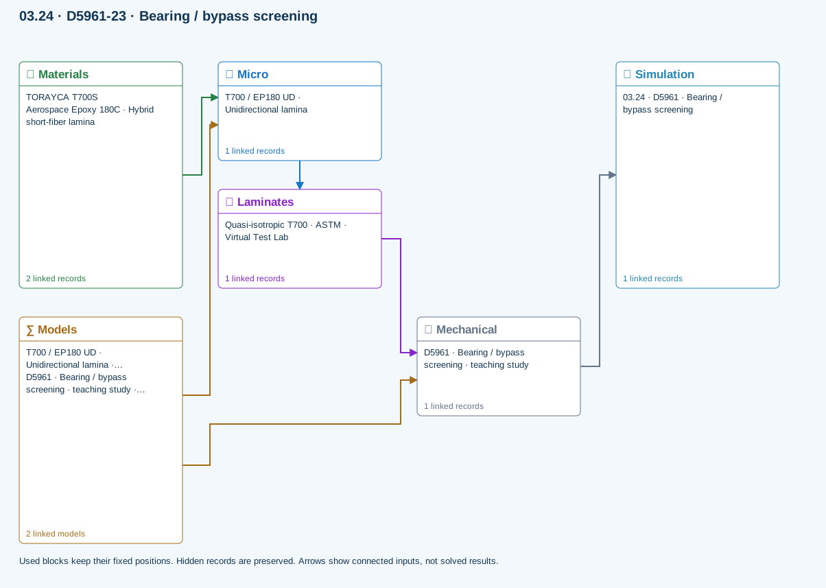
∑ Used models & submodels
Only models assigned to records used by this exercise are listed here. The full-layout option preserves the supplied starter records; no Workbench records are changed.
Halpin–Tsai · T700 / EP180 UD · Unidirectional lamina
One compatible homogenization model per Micro recipe. Separate recipes compare models; their predictions are not blended.
∑ Theory & assumptionsVirtual test · bearing bypass screening · D5961 · Bearing / bypass screening · teaching study
Single-pin nominal bearing, net-section and shear-out checks with independent measured allowables. Bypass tension is added to net-section load only. No contact, bolt preload, load redistribution or validated bearing–bypass interaction envelope.
Linked laminate reference state
Ply stiffness, thickness and orientation come from the linked laminate. Other thermal or structural analyses must be run separately.
Calibration & study controls
Teaching example
Specimen width: 36 mm
Hole diameter: 6 mm
Edge distance: 18 mm
Hole center to loaded free edge.
Pin force: 1000 N
Bypass tensile force: 500 N
Bearing allowable: 300 MPa
Net tensile allowable: 400 MPa
Shear-out allowable: 80 MPa
Data travelling between blocks
Micro → Laminates
Predicted ply stiffness, strength, density and expansion properties.
Materials → Micro
Constituent stiffness, strength, density and thermal / moisture properties.
Mechanical → Simulation
SIMULATION selects this case and its analysis model; the case owns its applicable cycle and input references.
Laminates → Mechanical
Ply angles and thicknesses, stiffness, mass and ply properties.
Models → Micro
Applied model assignment: Halpin–Tsai. Model parameters and formulation are used by Micro.
Models → Mechanical
Applied model assignment: Virtual test · bearing bypass screening. Model parameters and formulation are used by Mechanical.
D6484 · Open-hole compression
Nominal gross/net stress and demand relative to measured open-hole compressive strength for this geometry and layup. This is test-data screening, not an uncalibrated notch-strength prediction. No local buckling or kink-band simulation.
Equations, inputs and interpretation
σgross = P/(wt); σnet = P/[(w − d)t]; demand = σgross/XOHC.
XOHC is the measured gross-section compressive strength for this layup and hole geometry. Do not compare net stress with a gross-section allowable. This assessment does not reuse the Whitney–Nuismer tension model or predict compressive notch strength.
- Specimen width (mm)
- Hole diameter (mm)
- Applied force (N)
- Measured open-hole compressive strength (MPa)
Connected workflow
Only blocks on the exercise path are shown. This changes the view only, not the exercise records.
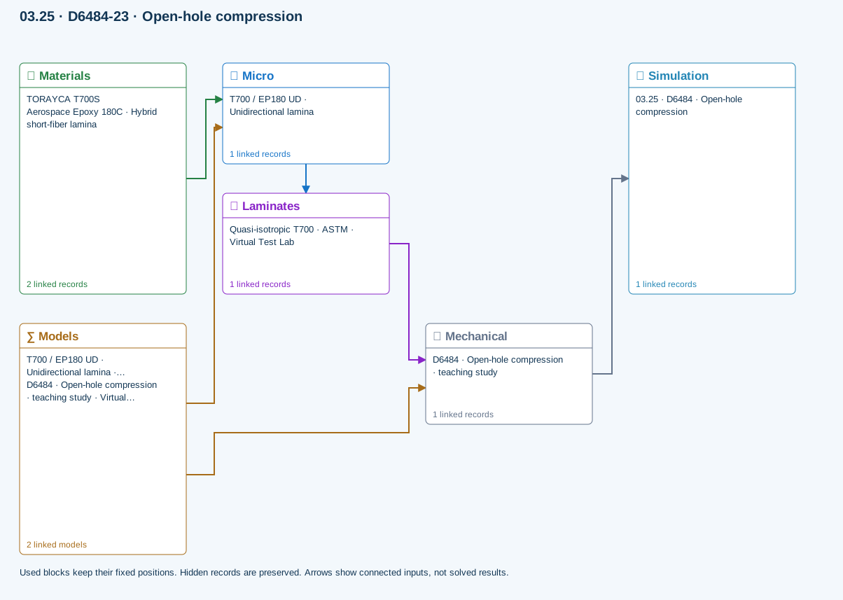
∑ Used models & submodels
Only models assigned to records used by this exercise are listed here. The full-layout option preserves the supplied starter records; no Workbench records are changed.
Halpin–Tsai · T700 / EP180 UD · Unidirectional lamina
One compatible homogenization model per Micro recipe. Separate recipes compare models; their predictions are not blended.
∑ Theory & assumptionsVirtual test · measured open-hole compression · D6484 · Open-hole compression · teaching study
Nominal gross/net stress and demand relative to measured open-hole compressive strength for this geometry and layup. This is test-data screening, not an uncalibrated notch-strength prediction. No local buckling or kink-band simulation.
Linked laminate reference state
Ply stiffness, thickness and orientation come from the linked laminate. Other thermal or structural analyses must be run separately.
Calibration & study controls
Teaching example
Specimen width: 36 mm
Hole diameter: 6 mm
Applied force: 1000 N
Measured open-hole compressive strength: 250 MPa
Data travelling between blocks
Micro → Laminates
Predicted ply stiffness, strength, density and expansion properties.
Materials → Micro
Constituent stiffness, strength, density and thermal / moisture properties.
Mechanical → Simulation
SIMULATION selects this case and its analysis model; the case owns its applicable cycle and input references.
Laminates → Mechanical
Ply angles and thicknesses, stiffness, mass and ply properties.
Models → Micro
Applied model assignment: Halpin–Tsai. Model parameters and formulation are used by Micro.
Models → Mechanical
Applied model assignment: Virtual test · measured open-hole compression. Model parameters and formulation are used by Mechanical.
D6742 · Filled-hole comparison
Compares user-measured open- and filled-hole compressive strengths using gross-section stress. Use matched layup, hole, environment and fastener condition. Filling a hole does not automatically recover strength; no fastener contact/preload model is applied.
Equations, inputs and interpretation
Demandopen = σgross/XOHC; Demandfilled = σgross/XFHC.
Compare matched measured open- and filled-hole compressive strengths. Pin fit, preload, environment and geometry must match the calibration basis. Filling the hole is not assumed to restore strength, and the curves show nominal demand scaling rather than predicted damage or load–deflection.
- Specimen width (mm)
- Hole diameter (mm)
- Applied force (N)
- Measured open-hole compressive strength (MPa)
- Measured filled-hole compressive strength (MPa)
Connected workflow
Only blocks on the exercise path are shown. This changes the view only, not the exercise records.
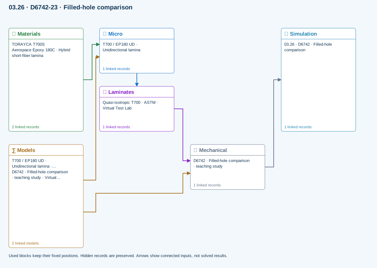
∑ Used models & submodels
Only models assigned to records used by this exercise are listed here. The full-layout option preserves the supplied starter records; no Workbench records are changed.
Halpin–Tsai · T700 / EP180 UD · Unidirectional lamina
One compatible homogenization model per Micro recipe. Separate recipes compare models; their predictions are not blended.
∑ Theory & assumptionsVirtual test · measured filled-hole comparison · D6742 · Filled-hole comparison · teaching study
Compares user-measured open- and filled-hole compressive strengths using gross-section stress. Use matched layup, hole, environment and fastener condition. Filling a hole does not automatically recover strength; no fastener contact/preload model is applied.
Linked laminate reference state
Ply stiffness, thickness and orientation come from the linked laminate. Other thermal or structural analyses must be run separately.
Calibration & study controls
Teaching example
Specimen width: 36 mm
Hole diameter: 6 mm
Applied force: 1000 N
Measured open-hole compressive strength: 250 MPa
Measured filled-hole compressive strength: 300 MPa
Data travelling between blocks
Micro → Laminates
Predicted ply stiffness, strength, density and expansion properties.
Materials → Micro
Constituent stiffness, strength, density and thermal / moisture properties.
Mechanical → Simulation
SIMULATION selects this case and its analysis model; the case owns its applicable cycle and input references.
Laminates → Mechanical
Ply angles and thicknesses, stiffness, mass and ply properties.
Models → Micro
Applied model assignment: Halpin–Tsai. Model parameters and formulation are used by Micro.
Models → Mechanical
Applied model assignment: Virtual test · measured filled-hole comparison. Model parameters and formulation are used by Mechanical.
D7136 / D7137 · Impact & CAI assessment
Incident energy from measured impact velocity; residual compressive strength from measured peak CAI force. Rebound energy estimates energy not returned to the striker, NOT damage energy. No impact/contact solver, damage-area prediction or energy-to-strength extrapolation.
Equations, inputs and interpretation
Eincident = mv²/2; Erebound = mvr²/2; XCAI = Ppeak/(wt).
Enter measured impact and rebound velocities, measured CAI peak force and pristine compressive strength. Energy not returned to the striker includes mechanisms other than damage. The strength-retention ratio is a measured comparison, not an energy-to-strength prediction. No synthetic impact pulse, damage footprint or full-wave impact solution is generated.
- Impactor mass (kg)
- Impact speed (m/s)
- Rebound speed (m/s)
- Specimen width (mm)
- Measured CAI peak force (N)
- Measured pristine compressive strength (MPa)
Connected workflow
Only blocks on the exercise path are shown. This changes the view only, not the exercise records.
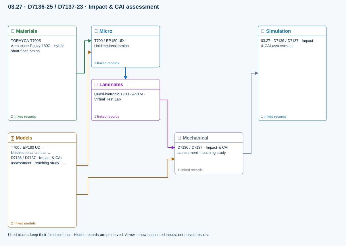
∑ Used models & submodels
Only models assigned to records used by this exercise are listed here. The full-layout option preserves the supplied starter records; no Workbench records are changed.
Halpin–Tsai · T700 / EP180 UD · Unidirectional lamina
One compatible homogenization model per Micro recipe. Separate recipes compare models; their predictions are not blended.
∑ Theory & assumptionsVirtual test · measured impact and CAI · D7136 / D7137 · Impact & CAI assessment · teaching study
Incident energy from measured impact velocity; residual compressive strength from measured peak CAI force. Rebound energy estimates energy not returned to the striker, NOT damage energy. No impact/contact solver, damage-area prediction or energy-to-strength extrapolation.
Linked laminate reference state
Ply stiffness, thickness and orientation come from the linked laminate. Other thermal or structural analyses must be run separately.
Calibration & study controls
Teaching example
Impactor mass: 5 kg
Impact speed: 2 m/s
Rebound speed: 0.5 m/s
Specimen width: 100 mm
Measured CAI peak force: 30000 N
Measured pristine compressive strength: 400 MPa
Data travelling between blocks
Micro → Laminates
Predicted ply stiffness, strength, density and expansion properties.
Materials → Micro
Constituent stiffness, strength, density and thermal / moisture properties.
Mechanical → Simulation
SIMULATION selects this case and its analysis model; the case owns its applicable cycle and input references.
Laminates → Mechanical
Ply angles and thicknesses, stiffness, mass and ply properties.
Models → Micro
Applied model assignment: Halpin–Tsai. Model parameters and formulation are used by Micro.
Models → Mechanical
Applied model assignment: Virtual test · measured impact and CAI. Model parameters and formulation are used by Mechanical.
What comes next?
Full impact/contact/damage prediction, fixture-resolved compression and shear, experimental compliance corrections, crack-growth validation and bearing–bypass interaction calibration remain separate development and validation work. This release does not claim those capabilities.
Chapter review
Report quantities with units, coordinate conventions, reference states and meaningful precision. Include warnings and excluded physics. Separate calculated response, engineering interpretation and design acceptance. Exercises belong in the Training Manual and may illustrate a chapter, but they do not define the theory or establish design allowables.
References and source sections
References are retained with the formulations they support. Software instructions describe implementation scope; a cited source does not establish independent validation of a CDS calculation.